-

Techniques for Calculating Relay Protection Settings
Use this Protection Relay Setting Calculator to calculate pickup current, time multiplier settings (TMS), operating time, coordination time interval (CTI), and plug setting multiplier (PSM) using fault current, CT ratio, and IEC 60255 curve parameters. For thermal overload protection (ANSI Device 49), the pickup is typically set at 115% to 125% of motor full-load amps depending on service factor. For overcurrent. This technical report refers to the electrical protections of all 132kV switchgear. All calculations are based on the available documentation/ information. These settings may be revaluated during the commissioning, according to actual and/or measured values. Presented at the 51st Annual Minnesota Power Systems Conference Saint Paul.
-
Busbar Connector Protection Box Usage
It is mainly used for insulation protection and safety protection of busbar connections in switchgear factories, power plants, and substations. In modern industrial electrical distribution systems, busbar systems serve as the backbone for power distribution, channeling electricity from main sources to various circuit protection devices and loads. The connection between molded case circuit breakers (MCCBs) and busbars represents a critical. The busbar joint protection box is made of radiation cross-linked polyolefin material. It has excellent physical, chemical and electrical properties. The high magnitude fault currents require high-speed. DEFINITIONS.
-
Protection level of busbar connectors
The International Electrotechnical Commission (IEC) sets out standardized testing procedures and benchmarks to ensure that busbar contact resistance remains within safe and acceptable limits. IEC standards are developed through international consensus and are used globally. The integrity of busbar joints is critical because. Busbars in power systems are the location where transmission lines, generation sources, and distribution loads converge. Because of this convergence, short circuits located on or near the busbar tend to have very high magnitude currents. The high magnitude fault currents require high-speed. Industry data shows that loose or improperly torqued busbar connections account for a significant percentage of electrical panel failures. Busbar distribution ensures these requirements are fully met. Performance criteria of. DEFINITIONS.
[PDF Version]
-
Several characteristics of relay protection are
To provide effective and reliable protection to the power system, a protective relay must have the following essential functional characteristics: Selective, Fast, Stable, Reliability, Sensitivity, Simple Construction and Installation Mechanism, and Cost-effective. A protective relay is an electrical switch which can automatically operate when a fault or any other abnormal conditions occur in the electrical system. It sends a signal to turn on the alarm or indicator or trip a circuit breaker to separate the faulty part from the healthy section. : 4 The first protective relays were electromagnetic devices, relying on coils operating on moving parts to provide detection of abnormal operating conditions such as. A protective relay is an intelligent electrical device designed to detect faults in power systems and initiate corrective actions such as tripping a circuit breaker. PSM – Plug Setting Multiplier (Current Setting Multiplier) What is PSM? 2).
[PDF Version]
-

Relay Protection Test Wiring Method
One approach to test the total protection system is to use primary injection techniques (see appendix H) that trigger protective relays and lockout relay, trip circuit breakers, and initiate annunciations and indications. If applicable, documentation is required detailing how verified protection segments overlap to ensure there is not a gap. The purpose of this Standard Work Practice (SWP) is to standardise and describe the method for testing of Ergon Energy protection relays for commissioning purposes. This SWP should be interpreted in conjunction with Standard for Substation Protection (V1. From a technician's perspective, master the unique skill of testing protection. When the transformer wiring type is Y/Y (Y0), the test wiring is very simple: when testing phase A, the tester IA is connected to the phase A of the high voltage side, and the tester IB is connected to the phase a of the low voltage side. After the neutral line of the high and low voltage sides is. Function: Use electronic components like transistors to perform switching. Applications: Frequency, undervoltage, and overcurrent protection.
[PDF Version]
-

Circuit Breaker Relay Protection Equipment Model
Microprocessor-based solid-state digital protection relays now emulate the original devices, as well as providing types of protection and supervision impractical with electromechanical relays.OverviewIn, a protective relay is a device designed to trip a when a is detected. The first protective relays were electromagnetic devices, relying on coils operating on moving par. Electromechanical protective relays operate by either, or. Unlike switching type electromechanical with fixed and usually ill-defined operating voltage thresholds. Electromechanical relays can be classified into several different types as follows: "Armature"-type relays have a pivoted lever supported on a hinge or knife-edge pivot, which carries a moving contact. These relays may.
-

Wired Channel for Relay Protection
With the addition of a line tuner, the CCVT (used for potential input to the protective relay) can be used to couple the PLC signal to the power line. Protection systems are used to isolate faulted parts of the system, protect the electric system from instability, and minimize equipment damage. Directional distance and overcurrent schemes, interfaced with communication equipment, send and receive logic-based information between relay te minals to determine if the fault is external or internal to the. Important benefits include limiting tripping to faulted line section, high-speed simultaneous clearing for all internal line faults, preventing overtripping on external faults, and reducing transmission line and station damage. Applications of the concepts to accepted transmission line-protection schemes are also presented.
-
What is ARD in relay protection
The AR/ARD relays are electromechan-ical convertible contact relays. Earlier relays do not necessarily incorporate all the features described. The Delta ARD4 User Guide is designed as a. Smart Motor Protector ARD2 Series (hereinafter referred to as Protector) utilizes advanced single chip technology and is featured in the strong anti-interference, stable and reliable running, digitalization, intelligence and networking. The protector can protect the motor from timeout startup. The ARD3M intelligent motor protector is suitable for low-voltage motor circuits with rated voltage up to 660V and integrates protection, measurement, control, communication, operation and maintenance. AR. Shop Now ARD Series Motor Protection Relay.
-
Steps for Short Circuit Calculation in Relay Protection
Voltage levels, transformer ratings and impedances, line lengths and impedances, generator/motor data. Select fault location Choose busbars or nodes where faults will be studied. Apply IEC. A short circuit occurs when an unintended low-impedance path forms between: Physical Causes: Critical Applications: ⚠️ Safety Critical: Incorrect fault current calculations can result in explosive equipment failures, arc flash incidents causing severe burns, and system-wide cascading failures. The principle is to grade the operating times of the relays in such a way that. The scope of study involves calculating the settings for protective relays to achieve selectivity during faults ocurring in the electrical network for the 13. In OC relays the coordination is based on the relay time-current characteristics of instantaneous and/or time delay units. Instantaneous units should be set so they. As of this update, Service Disconnect Switches, Surge Protective Devices, Switchboards, Switchgear, and Panelboards, Industrial Control Panels, Motor Controllers, Elevators, Industrial Machinery, and Transfer Equipment are all required to have short-circuit current ratings.
[PDF Version]
-
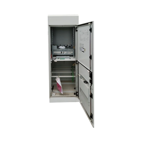
Fire safety requirements for relay protection compartments
In order to effectively resist the effects of fire, heat, and smoke, a fire-rated barrier must be complete and whole. There cannot be any openings or holes in the wall such as open doors, windows, or holes f.
-
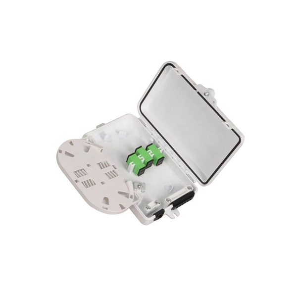
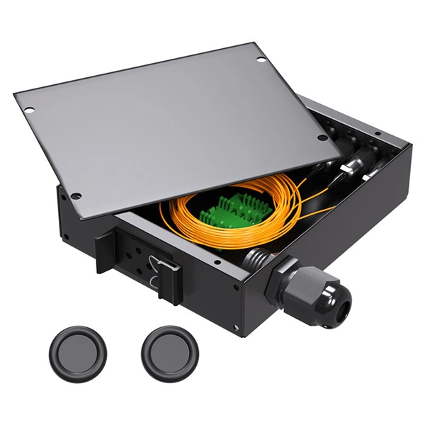
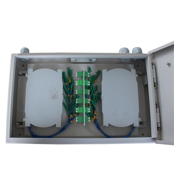
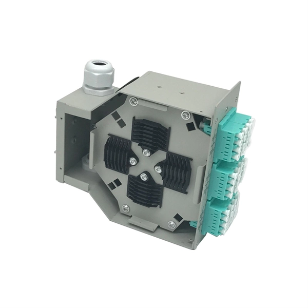
Lightning protection and grounding of mobile optical distribution boxes
This Recommendation provides guidance on protecting indoor distribution systems for mobile communication in large-scale buildings from lightning and safety risks. It emphasizes compliance with standards like IEC 62305-3, IEC 62305-4, IEC 60364 series, and ITU-T K. 21 for effective. We make safe, reliable and high-quality solutions for every spec and project. Lightning protection needs vary according to each specific facility. It is located at an elevation such that a line passing through the static wire and the outermost conductor below it is at a 30° aximum angle with a vertical line. ERICO® has complete telecommunications applications solutions to help protect the facility against electrical noise, lightning induced surges and transients caused by. Ground rods are the most common grounding electrode found on distribution circuits.
[PDF Version]
-
Relay protection panel reset
Operate the mechanical reset lever or pushbutton on the lockout relay, or use the relay's HMI/SCADA interface for electronic relays. For microprocessor relays, use the front panel or remote interface to acknowledge and reset the lockout/trip condition. In this comprehensive guide, we will delve into the essential steps for resetting a relay efficiently and effectively. From troubleshooting common issues to performing the reset process step-by-step. How can I reset the Alarm or Trip on 857 Motor protection relay? There are two status indicators named "Alarm" and "Trip" on the front panel that is mapped within the Output Matrix. #relay #lockoutrelay #electrical #howtoresetrelay #86relay #mastertriprelay lockout relay function lockout relay wiring diagram lockout relay 86 protection lockout relay wiring lockout relay operation lockout relay 86. View all of Eaton's protective relays PowerPort-E can not connect to the device. The settings in a 751 shouldn't be reset because of a loss of power.
[PDF Version]