-
Size parameters of edge data centers for smart cities
Hyperscale centers are usually located in cities and can typically house 10,000 racks with a capacity in excess of 80 megawatts (MW). Edge data centers by comparison, have a smaller capacity between 500 kilowatts to 2 MW and, as the name suggests, are located on the outer edge of. Edge data centers are compact computing facilities strategically placed close to where urban data is generated, enabling low-latency processing, local analytics, and greater resilience for smart city services. This proximity reduces latency from 50-100 milliseconds down to single digits, which matters for applications where every millisecond of. Smart cities are being built on a simple expectation: data must move faster than ever, and decisions must happen in real time. It requires lots of planning and preparation to ensure that it can deliver the necessary end goals.
[PDF Version]
-
Bolivia Data Center Solution Quotation
We currently have 5 data centers listed, from 2 markets in Bolivia (Bolivia). Click on a market below, to explore its data center locations. Save the trouble of contacting the providers yourself, check out our Quote Service. Do. The data center procurement tool trusted by leading enterprises We work with you to understand your goals and technical requirements of your data center project. The Data Center market is a critical segment of the technology industry focusing on supplying and managing physical infrastructure necessary for hosting and. Keep up-to-date with all the latest news, articles, event and product updates posted on Developing Telecoms.
-
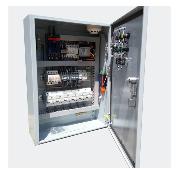
Configuration of circuit breakers for home data center distribution boxes
This guide shows you how to organize circuit breaker wiring properly. You will learn to build a safe, efficient, and professional electrical system today. Circuit breaker wiring configurations involve organizing main switches, busbars, and branch breakers within a distribution box. What Are Data Center Circuit Breakers? Data center circuit breakers are components of a data. Recommendations on how to select the correct circuit breakers and trip systems, best placement of circuit breakers in the PDUs and RPPS, and proper line and load Recommendations on how to select the correct circuit breakers and trip systems, best placement of circuit breakers in the PDUs and RPPS. Choosing the right size and setup for your distribution box keeps your electrical system safe and working well. Messy distribution boxes are dangerous and very hard to fix. Configuration: The switchgear is typically composed of multiple cubicles, including an incoming unit, outgoing unit, voltage metering unit, and bus section. Each cubicle is designed.
[PDF Version]
-
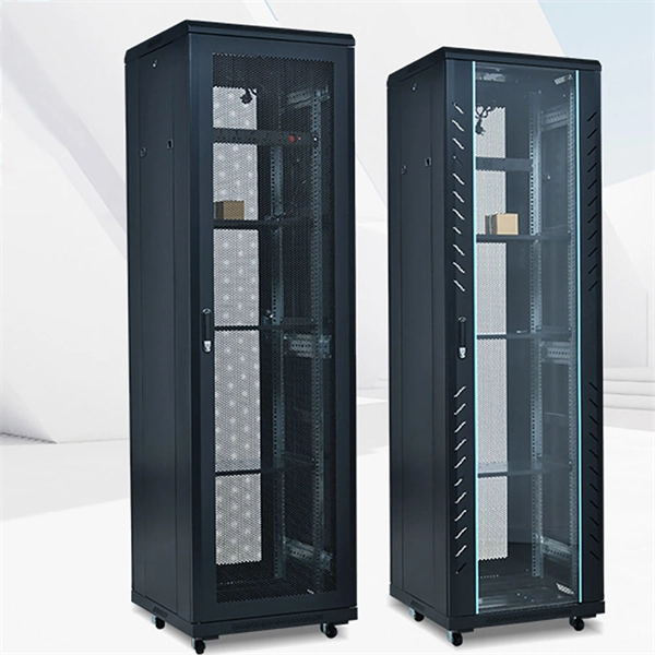
Internal Structure of Data Center Racks
Rack frame: The structural skeleton that holds all mounted devices. Shelves and drawers: Used for non-rackmountable devices or. Crucial considerations include the types of IT racks for housing essential systems, the decision between preconfigured and customized solutions (given the tradeoffs among price, delivery times, and effort), and the choice between open and closed frame racks. Relevant factors include access. Data center racks are metal frames used for organizing IT equipment such as servers and switches. Selecting the right rack requires evaluating its height (U), depth, width, weight capacity, airflow design, power integration. Below, we outline four common slab types frequently considered in modern Data Center projects, along with their pros and cons: In this approach, a fully reinforced concrete slab is poured and cured on-site using traditional formwork. Regular. BIM | Data | AI | Helping Global Design Firms Scale with Dedicated BIM Documentation | Founder @ Au-mm | Architectural BIM Lead - Mission Critical Projects | Faculty When people outside the field hear "data center," they usually imagine a cold, dark room filled with servers blinking in sync.
[PDF Version]
-
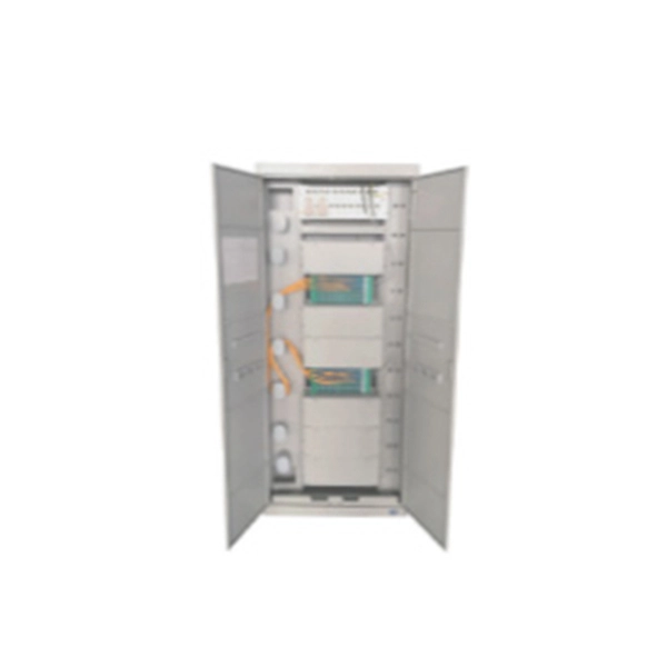
Are ODF fiber optic cables typically placed in data centers
ODFs are typically installed in data centres, telecommunication hubs and central offices. It serves for fiber optic splicing, termination, storage of excess fibers, and protection. It organizes fiber connectors, patch. An Optical Distribution Frame is a specially designed enclosure used to manage, organise, connect and protect fibre optic cables. With the rise of high-density data centers and FTTH systems, traditional ODF designs are being complemented by MPO/MTP-based fiber patch panels.
-
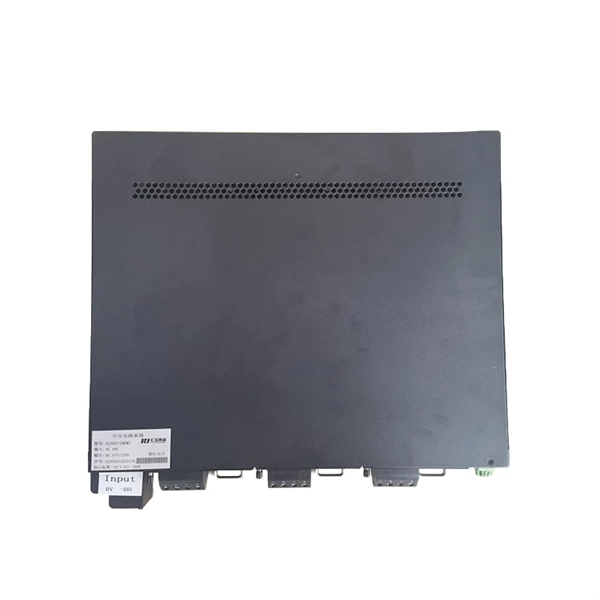
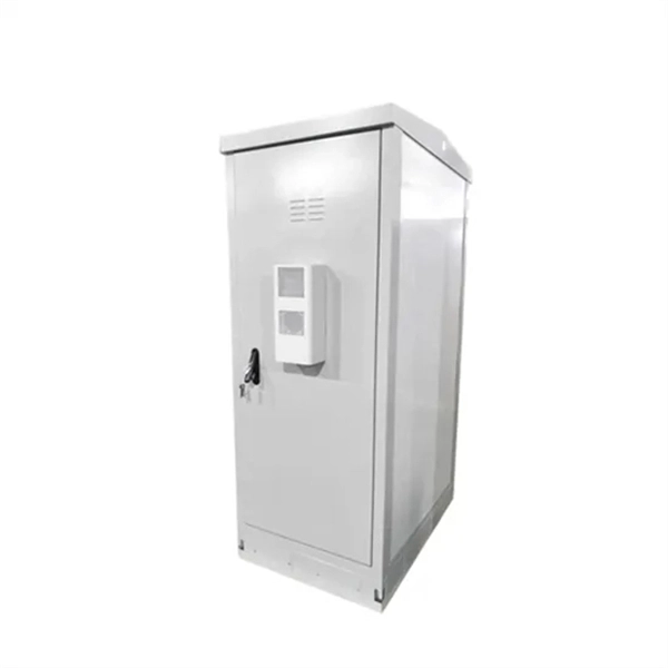
Data Center EMS 50kW for Mining Use
This 50KW/50KWH battery system includes ten LiFePO₄ modules, a 50KW inverter, and a smart EMS/BMS, all housed in a compact IP54 cabinet. It delivers reliable storage for peak load shaving, solar optimization, or backup support. The UESS-CAB 50–100F is an all-in-one outdoor energy storage cabinet designed for factories, data centers, mining sites, cold-chain warehouses, and microgrids. Built for commercial use, the system is robust, space-efficient, and. Neither the United States Government nor any agency thereof, nor any of their employees, nor any of their contractors, subcontractors or their employees, makes any warranty, express or implied, or assumes any legal liability or responsibility for the accuracy, completeness, or any third party's use. Our 50kW commercial solar ESS (Energy Storage System) integrates cutting-edge lithium battery technology and advanced energy management systems to provide reliable energy solutions for industrial parks, commercial centers, and remote areas. It includes management system, and energy management system. The various user-side applications.
[PDF Version]
-
Emergency Circuit Design for Distribution Boxes
Size emergency and standby circuits with NEC 700/701, IEC 60364-5-56, UPS/generator transfer paths, and real voltage-drop examples. On a recent plan review, the riser looked clean: NEC 700 emergency lighting, a listed transfer switch, copper conductors, and breakers sized. Emergency and standby power systems are designed to provide an alternate source of power if the normal source of power, typically the electric utility service, should fail. Reliability of these types of systems is critical and good design practices are essential. Classification of Emergency and. Emergency system circuits supply power to critical life safety loads such as emergency lighting, fire alarm systems, fire pumps, smoke control systems, and essential communication and control circuits. Correct wiring design for emergency system circuits is essential to maintain power integrity. The National Electrical Code (NEC) Section 700. Under no. Another is to limit what qualifies as an “emergency load,” so the emergency system powers only what is needed to save human life (Fig.
[PDF Version]
-
Requirements for Relay Protection Design
The IEEE standard for protection relays refers to a collection of guidelines developed by the Institute of Electrical and Electronics Engineers. This document provides recommendations, background and philosophy on relay protection that is not available in M07. They are intended to quickly identify a fault and isolate it so the balance of the system continue to run under normal conditions. For professionals working in utilities, industries, or renewable energy systems, understanding these standards is not optional—it is essential. This handbook covers the code of practice in protection circuitry including standard lead and device numbers, mode of connections at terminal strips, colour codes in multicore cables, dos and donts in execution.
-
Optical Module Lens Design
Looking to learn about optics and optical design? Learn the basics of optics needed to begin designing optical systems in this educational, online Fundamentals of Optics course co-created by E.
-
Relay Protection Design Guidelines
This handbook covers the code of practice in protection circuitry including standard lead and device numbers, mode of connections at terminal strips, colour codes in multicore cables, dos and donts in execution. This document supplements PJM Manual 07 which contains the minimum design standards and requirements for the protection systems associated with the bulk power facilities within PJM. The IEC standard for relay coordination provides clear guidelines and methodologies to ensure that protective relays work in harmony to isolate only the faulty section of the system while keeping the rest. Protective relays and devices have been developed over 100 years ago to provide “last line” of defense for the electrical systems.
-
Fiber optic cable design reserve length
Standard/default length is 2 inches (reference), as produced by most label manufacturers. Marking details are based on MIL-STD-130 and will be legible and permanent. • Fiber optic cables are often custom cut to match required lengths for each cable run, or you can order a reel matching your total length and cut segments yourself. It's advisable to include a safety buffer when ordering, with an additional 10% being common practice, despite careful measurement of. Fiber optic network design refers to the specialized processes leading to a successful installation and operation of a fiber optic network. To calculate teh total number of fiber strands that will be required for the fiber optic cable installation, many people makes the mistake of underestimating the total. All lengths are calculated in a base unit, then converted. Reel count is ceil (Total ÷ ReelSize), and the rounded order length equals Reels × ReelSize. (FOA) was founded in 1995 to help develop the workforce to build the fiber optic networks to support a rapid expansion in communications and the Internet.
[PDF Version]
-
Multimode fiber supports the largest data packet size
MMF supports high data rates—up to 100 Gbps—over distances typically ranging from 300 to 550 meters, depending on fiber type (OM3, OM4, OM5). Multi-mode links can be used for data rates up to 800 Gbit/s. Multi-mode fiber has a fairly large core diameter that enables multiple light modes to be propagated and limits the maximum length of a transmission link because of modal dispersion. 1 defines the most widely used. Single Mode Fiber (OS2) offers near-infinite bandwidth and reach (up to 40km+), making it the 2026 standard for AI and core backbones. Multimode Fiber (OM4/OM5) remains the most cost-effective solution for short-reach data center links (<150m) due to its lower-cost VCSEL-based transceivers. In the market, there are five types of multimode optical.