-
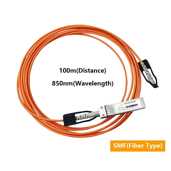
Should fiber optic cables be used with a router or a control panel
Yes, fiber internet requires specific equipment including an Optical Network Terminal (ONT) and a compatible router. The ONT converts fiber-optic light signals into electrical signals your devices can use. A fiber router is a networking device designed specifically to work with a fiber-optic internet connection. This. Running copper Ethernet cables and coax cables outdoors can put your entire home or office network at risk for power surges from lightning strikes. In many cases, this can instantly destroy all.
-
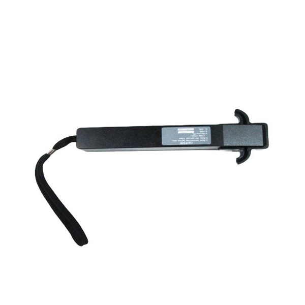
Relay protection panel reset
Operate the mechanical reset lever or pushbutton on the lockout relay, or use the relay's HMI/SCADA interface for electronic relays. For microprocessor relays, use the front panel or remote interface to acknowledge and reset the lockout/trip condition. In this comprehensive guide, we will delve into the essential steps for resetting a relay efficiently and effectively. From troubleshooting common issues to performing the reset process step-by-step. How can I reset the Alarm or Trip on 857 Motor protection relay? There are two status indicators named "Alarm" and "Trip" on the front panel that is mapped within the Output Matrix. #relay #lockoutrelay #electrical #howtoresetrelay #86relay #mastertriprelay lockout relay function lockout relay wiring diagram lockout relay 86 protection lockout relay wiring lockout relay operation lockout relay 86. View all of Eaton's protective relays PowerPort-E can not connect to the device. The settings in a 751 shouldn't be reset because of a loss of power.
[PDF Version]
-

Relay Protection Control Program
NERC has developed Standard PRC-005, to ensure that all transmission and generation protection systems affecting the reliability of the BES are maintained and tested. June 15-19, 2026 This course provides foundational training in the areas of Protective Relays, Protection Schemes, Instrument Transformers, and other equipment used in Power System Protection and Controls. Laboratory exercises will cover proper relay maintenance, specific. Relay systems protect high-voltage equipment and transmission lines to ensure safe, stable systems. The course provides basic guidelines for relay application and settings calculation.
-
Two channels of relay protection for the network control building
The dominance of dual-setting directional overcurrent relays (DS-DOCRs) based protection schemes and associated high-reliability requirements require rigorous verification of these schemes before deployment.
-
A Comprehensive Guide to Seismic Supports for Palestinian Bridge Structures
Hatem Alwahsh f• Dynamic analysis: the analysis shall be based on an appropriate ground motion representation and shall be performed using accepted principles of dynamics. The main methods of dyn.
-
Boost Module Photovoltaic Panel
This example uses a boost DC-DC converter to control the solar PV power. The boost converter operates in both MPPT mode and voltage control mode. The model uses the voltage control mode only when t.
-
How to test a photovoltaic panel with a multimeter
Testing solar panels is easy with a multimeter! To test the current, simply connect the multimeter to the panel's output. Whether you're a seasoned solar enthusiast or a newcomer to the world of renewable energy, knowing how to use a multimeter to test your solar panels is a valuable skill that can empower you to take control of your energy production. Measure Voc (open circuit voltage) — if it reads 0V, the panel or wiring is dead. If Voc is normal but the system is not producing, the problem is downstream. Solar panels are usually tested under standard conditions using a light source that mimics the light from the sun on a clear day. This helps you spot issues early and keep your system running efficiently.
-
How to print the optical module panel
You can print modules using a standard Print window, or the Print Preview window. A standard Print window is displayed that lets you specify which printer you want to use, what pages you want to. If an optical module on an interface is faulty, you can run the display commands to view information about the optical module. The fiber shuffle and MPO fan-out unit mechanically holds 14 and 10 passive. CommScope has collaborated with DYMO, a brand of RHINO Professional Labeling Tools and part of Newell Rubbermaid, to support the development and distribution of pre-formatted electronic templates, making the labeling of structured cabling systems easier and more efficient for installers., through the identification of the module information can be detected by the module and. LabVIEW tutorials on how to print front panel and block diagram of VI or application in LabVIEW. ✮ Facebook: / labview-advantage-209506362772803.
[PDF Version]
-
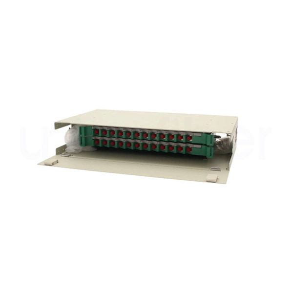
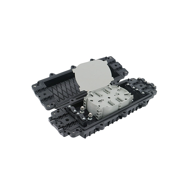
How to use a 96-core fiber optic patch panel
These high-density fiber patch panels allow a mix-and-match of e2XHD fiber and copper snap-in cassettes - up to 96 LC fibers or 48 copper ports per RU. Cassettes quickly snap in and pull out of the panel, making installation and changes easier than ever. These individual strands will then connect to electronic devices. This is precisely the problem the MPO/MTP® patch panel was designed to solve. Frankly, if you're deploying 40G, 100G, or higher, you can't afford to ignore this technology. The 96 Core Slide Drawer Patch Panel 1U UHD MPO/MTP-LC 4 Cassette is a versatile solution for high-density fiber management in data centers and telecom networks. Designed for 19″ rack-mount cabinets, it accommodates up to four HD MPO/MTP-LC cassettes, providing a plug-and-play system that. OptoSpan's WM-96 Wall Mount Termination and Splicing Enclosures provide a convenient, secure and organized housing for fiber optic connections and terminations, as well as a central point for splicing fiber optic cables for indoor or outdoor installations.
[PDF Version]
-
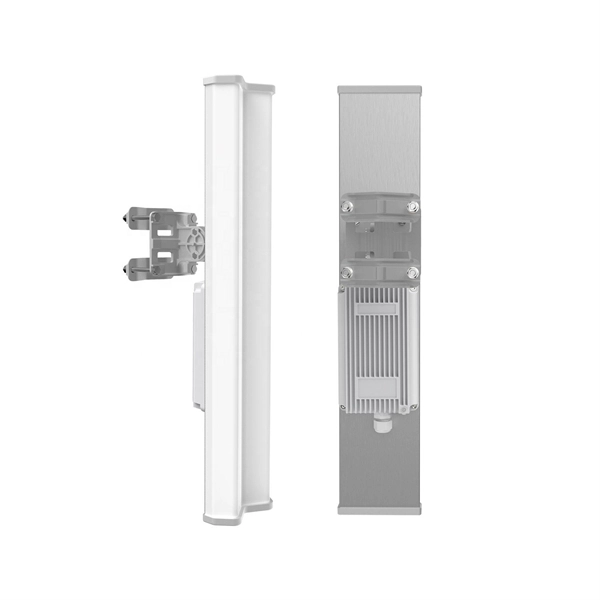
Industrial Ethernet Dual-Port Information Panel Armor
Solid-state equipment has operational characteristics differing from those of electromechanical equipment. Safety Guidelines for the Application, Installation and Maintenance of Solid State Controls (Publica.
-
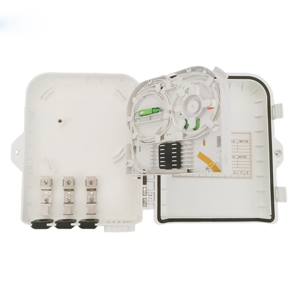
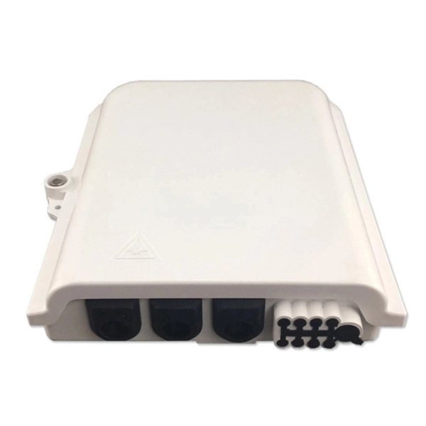
How to set up a network using a fiber optic panel
If your ISP doesn't require a technician to set up your connection, these are the steps to self-install fiber internet: Locate your fiber network terminal. Connect the fiber terminal to the network box. Once you understand the basic concepts, you can check out my Recommended Equipment section toward the bottom of the. This guide walks you through the complete fiber installation process, from checking availability to optimizing your Wi-Fi network performance. Fiber transmits data using light signals through glass strands, delivering faster speeds and lower latency than cable or DSL connections that rely on. However, setting up a fiber optic connection to your router can seem daunting if you're unfamiliar with the process. Jump to: How to. In this article we'll break down how fiber internet is installed - from the network fiber drop outside your house to the in-home setup with your router and gateway - and what you should expect at each stage. Fiber optic internet is generally installed in the following 5 steps, which we'll dive.
[PDF Version]
-
Internal relays of relay protection devices
The fault can be located upstream or downstream of the relay's location, allowing appropriate protective devices to be operated inside or outside of the zone of protection.OverviewIn, a protective relay is a device designed to trip a when a is detected. The first protective relays were electromagnetic devices, relying on coils operating on moving par. Electromechanical protective relays operate by either, or. Unlike switching type electromechanical with fixed and usually ill-defined operating voltage thresholds. Electromechanical relays can be classified into several different types as follows: "Armature"-type relays have a pivoted lever supported on a hinge or knife-edge pivot, which carries a moving contact. These relays may.