-

Switches are all 10 Gigabit optical
To implement different 10GbE physical layer standards, many interfaces consist of a standard socket into which different physical (PHY) layer modules may be plugged. PHY modules are not specified in an official standards body but by (MSAs) that can be negotiated more quickly. Relevant MSAs for 10GbE include (and related X2 and XPAK), and. When choosing a PHY.
-
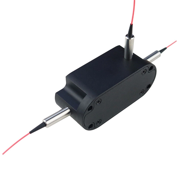
Optical modules are used in switches
Switch optical modules, which convert electrical signals to optical signals and vice – versa, and optical interfaces, which serve as the physical connection points, play a pivotal role in determining the speed, distance, and reliability of data transmission. Everything you need to build an optical network from end-to-end. Common optical module types such as SFP. SFP (Small Form-factor Pluggable) is a compact, hot-pluggable network interface module used to connect network devices (switches, routers, firewalls) to fiber optic or copper cables. Think of it as the “translator” for your network equipment, converting electrical signals into optical signals. Describes what an optical module is and FAQs, including the fundamentals, appearance and structure, key performance counters, common types, and naming conventions of optical modules, causes of optical module failures and corresponding protection measures, types of optical modules supported by. An optical transceiver module, often simply called an optical module, acts as a signal conversion interface in fiber optic networks.
[PDF Version]
-
How to connect and splice optical cables in series
The simplest method: connect two cables pre-connectorized via a coupler (also called an adapter). The coupler aligns the two ferrules of the connectors using a zirconia sleeve. Before jumping into the physical steps, it's important to understand the two primary methods of fiber splicing: fusion splicing and. Fiber optic cable splicing involves joining two fiber optic cables together. Another method of connecting optical fibers is termination or connectorization, which consists of processing the end of a fiber optic bundle so that it can be connected to other fibers or devices through fiber optic. Connecting fiber optic cables requires precision and care due to the delicate nature of the fibers. At Turn-Key. Proper connection of fiber optic cables is essential to harness these benefits fully, as even minor errors can lead to significant performance issues like signal loss.
[PDF Version]
-
Huawei Optical Module Model Series List
Huawei S series devices support optical modules of the following encapsulation types: CFP, QSFP+, QSFP28, XFP, SFP, eSFP, and SFP+. All optical modules are hot swappable. Huawei's data center network leverages advanced optoelectronics technologies to establish high-performance connections, ensuring reliable interconnectivity across data center infrastructures. GE to 100GE full-scenario optical interconnection solutions for general-purpose computing. Together, they ensure resilient data center interconnectivity and empower. On an optical network, a sender needs to convert electrical signals into optical signals before sending them to a receiver, and the receiver needs to convert received optical signals into electrical signals. Huawei's main business scope is switching. ers, only the short transmission distance is supported. Whether optical attenuators need to be deployed at the receive end o If an optical module has been certified by Huawei, its label contains "HUAWEI", as shown in Figure 8-1. In the display elabel command output, the Manufactured field displays a date later than 2013-07-01.
[PDF Version]
-
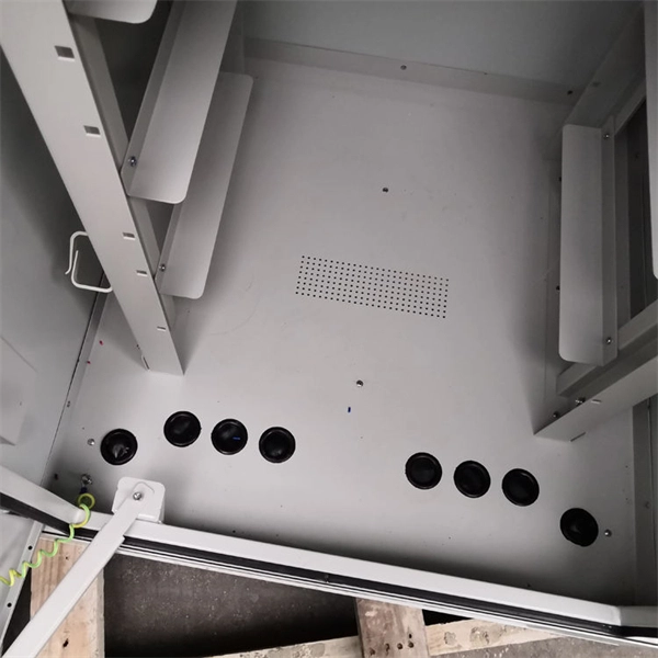
Composition of optical distribution box
It is widely adopted in FTTx cabling for both fiber cabling, provides the connection between fiber optic cables and passive optical splitters. Fiber Distribution box contains the shell, the internals (supporting frame, set fiber disc, fixing device) and optical fiber. The fiber distribution box, a crucial component in optical fiber networks, serves a dual purpose of managing and protecting optical fibers while facilitating their efficient distribution. Whether you're building a central office, data center, or FTTx distribution network, understanding the right ODF. ication and relevant standards over the range of optical wavelengths from 1260nm to 1625nm. However, component desi n should also take account of future requirements to extend operating wavelength to 1675nm. Cross-con-nections and direct connection can be two ways to.
[PDF Version]
-

Is the H3C switch an optical port or an electrical port
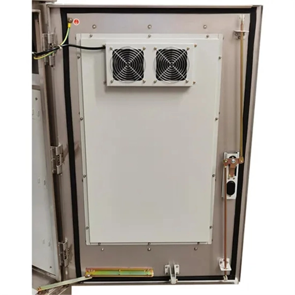
H3C S1850V2-X switch series comes with standard Gigabit copper ports and Ten-Gigabit optical ports, making it a good fit for complex network environments and network expansion. H3C FS6300V2-EI series switches are a new generation of high-performance, high-port density, high-security Layer 3 Ethernet switches developed by H3C Technology Co. (hereinafter referred to as H3C) using industry-leading ASIC technology, supporting IPv4/IPV6 Dual-stack management and. A Combo port can operate as either an optical port or an electrical port. Inside the device there is only one forwarding interface. You can specify a Combo port to operate as an electrical port or an. This video provides a comprehensive guide on configuring and troubleshooting Combo ports on H3C Ethernet switches. Reasonable cable routing can improve efficiency by facilitating installation and removal of fan trays, and some other components. Interface cables are routed through the. Packaging Details:1. Rated voltage range: -48 ~ -60V DC.
[PDF Version]
-
How to connect optical cables to split them into multiple paths
Optical couplers can split or join signals in fibers. These devices work both ways, which helps strong network communication. For example, optical splitters send light to many output ports. You can also use them to join light from. Before attempting to split a fiber optic cable, gather the necessary tools and equipment: Fiber Optic Splitter: This device divides a single optical signal into multiple signals. It typically consists of an MPO connector on one end, which can accommodate multiple fibers, and multiple connectors (such as LC or SC) on the other end, each. Optical splitters offer a cost-effective and dependable solution across various fiber optic applications. Also known as optical splitters, fiber splitters, or beam splitters, these devices are integrated waveguides ensuring wide bandwidth and minimal loss in high-frequency applications. This device takes the incoming light signal and divides it into multiple paths, allowing the signal to be sent to multiple devices.
[PDF Version]
-
How to waterproof the connecting pipe of the optical distribution box
The cap-type splice box uses a heat-shrinkable sleeve to seal the lead-in part of the optical cable into the splice box, and connects the line optical cable and the splice box as a whole. The upper and lower covers squeeze the rubber ring to make it waterproof. Extended size. Waterproofing an electrical connection is all about creating a bulletproof barrier against moisture.
-
How to determine light attenuation of red light using an optical power meter
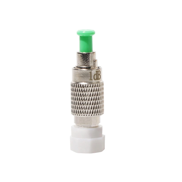
Optical attenuation compares input and output power on a logarithmic scale. When powers are in linear units, the loss in decibels is: Attenuation (dB) = 10 × log10 (Pin / Pout) If the link length L is provided, the attenuation coefficient is: Coefficient (dB/km) =. Analyze optical power drop across fibers and links. Switch units, lengths, and calculation modes easily. Needed when attenuation is an. Optical power, required for measuring source power, receiver power and, when used with a test source, loss or attenuation, is the most important parameter and is required for almost every fiber optic test. Backscatter and wavelength measurements are the next most important and bandwidth or. Optical power meters are a key element in the optimization and maintenance of such optical networks and of their components. But, for designers, just starting to work in the fiber-optic design space, measuring attenuation can seem like a monumental task.
[PDF Version]
-
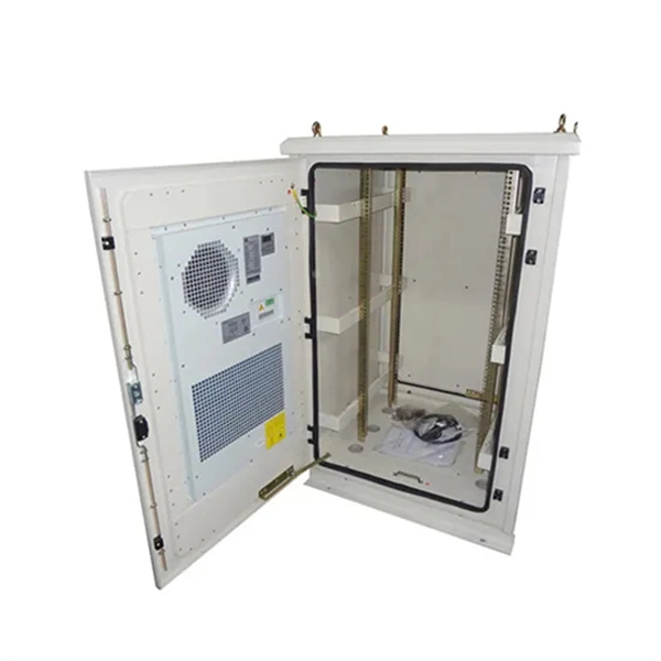
What is the fiber optic splice tray in the optical distribution box
• Splice Tray: This compartment is designed for fiber splicing and storage. It features slots or holders that secure spliced fibers, protecting them from bending, physical damage, or external stress. What is a Fiber Splice Tray Used for? With the increasing development of optical fiber networks, optical fiber terminals using fusion splicing or mechanical fusion have become common. Because optical fibers are sensitive to pulling, bending, and crushing forces, use fiber splice trays to provide. With the growth of FTTH, FTTx, and telecom fiber networks, the management of fiber optic splicing plays an increasingly important role in network reliability, performance, and maintainability. Inside splice closures, cabinets, and distribution frames, dozens or even hundreds of fibers need to be. Fiber Distribution Boxes (FDBs) are critical components in modern telecommunications infrastructure, particularly in fiber optic networks. Typically made from durable materials like plastic or.
[PDF Version]
-
Armenia Passive Optical Network Low Voltage Circuit
INCRIPT provides project development and management, turnkey solution implementation, installation, commissioning, and technical maintenance of low-voltage systems. The Relevance Inspector will open in the Coveo Administration Console. Our integrated circuits and reference designs help you create optical network terminal (ONT) units that enable high-speed data connections for today's passive optical networks. Use the resources below to design a system with our. INCRIPT emerges as a proficient systems integrator with over a decade of extensive experience in the Armenian market. Since its inception, the company has continuously evolved, refining its expertise in designing, building, and upgrading IT infrastructure and engineering systems. We offer turnkey. This paper presents the design and implementation of a passive optical network (PON) based on a gigabit-capable passive optical network (GPON) standard to deliver fiber-to-the-home (FTTH) services in a small-town setting. 5% of people in rural areas have access to the Internet, but only 73. The construction and deployment.
[PDF Version]
-
OPGW optical cable manufacturer in Lebanon
APAR designs and manufactures OPGW cables using advanced stranding technology, precision fiber integration processes, and stringent quality control systems. is a leading telecommunication company and a leading provider of telephony systems, networking, security and CCTV systems, Home Automation Systems, and Nurse Call System. IMATEL was founded in 1986 as a telecommunication provider. OptiLink was built on a simple belief: world-class fiber infrastructure shouldn't be reserved for the largest enterprises. This comprehensive analysis profiles the Top 10. Optical fiber composite overhead ground wire (OPGW) 1. Installed at the top of high-voltage and extra-high-voltage transmission lines, OPGW cables provide lightning. OPGW is primarily used by the electric utility industry, placed in the secure topmost position of the transmission line where it “shields” the all-important conductors from lightning while providing a telecommunications path for internal as well as third party communications.
[PDF Version]