-
Two channels of relay protection for the network control building
The dominance of dual-setting directional overcurrent relays (DS-DOCRs) based protection schemes and associated high-reliability requirements require rigorous verification of these schemes before deployment.
-
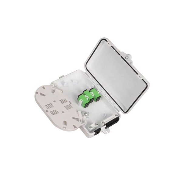
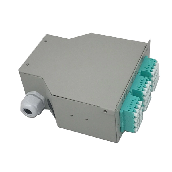
Centralized Control Distribution Box Configuration
Choose the right box based on environment (indoor/outdoor), load capacity, and durability. Check for proper IP/NEMA ratings and material quality. It is a way to standardize installation, simplify service, and create a cleaner architecture for commercial lighting systems. In North American projects, enclosures and enclosure-mounted accessories often relate to UL 50 / UL 50E, while complete. This article presents engineering best practices for designing your systems and dealing with issues you may encounter along the way. The central question How much to centralize or distribute really has two aspects to sort out: the control itself and the I/O subsystems. Industrial computer technology allows fast utilization of modern. Indication Lights: These provide visual availability and status of mains power supply. Each component plays a specific role. Ensure safe placement: install in.
[PDF Version]
-

Relay Protection Control Program
NERC has developed Standard PRC-005, to ensure that all transmission and generation protection systems affecting the reliability of the BES are maintained and tested. June 15-19, 2026 This course provides foundational training in the areas of Protective Relays, Protection Schemes, Instrument Transformers, and other equipment used in Power System Protection and Controls. Laboratory exercises will cover proper relay maintenance, specific. Relay systems protect high-voltage equipment and transmission lines to ensure safe, stable systems. The course provides basic guidelines for relay application and settings calculation.
-
Fire safety requirements for relay protection compartments
In order to effectively resist the effects of fire, heat, and smoke, a fire-rated barrier must be complete and whole. There cannot be any openings or holes in the wall such as open doors, windows, or holes f.
-
Steps for Short Circuit Calculation in Relay Protection
Voltage levels, transformer ratings and impedances, line lengths and impedances, generator/motor data. Select fault location Choose busbars or nodes where faults will be studied. Apply IEC. A short circuit occurs when an unintended low-impedance path forms between: Physical Causes: Critical Applications: ⚠️ Safety Critical: Incorrect fault current calculations can result in explosive equipment failures, arc flash incidents causing severe burns, and system-wide cascading failures. The principle is to grade the operating times of the relays in such a way that. The scope of study involves calculating the settings for protective relays to achieve selectivity during faults ocurring in the electrical network for the 13. In OC relays the coordination is based on the relay time-current characteristics of instantaneous and/or time delay units. Instantaneous units should be set so they. As of this update, Service Disconnect Switches, Surge Protective Devices, Switchboards, Switchgear, and Panelboards, Industrial Control Panels, Motor Controllers, Elevators, Industrial Machinery, and Transfer Equipment are all required to have short-circuit current ratings.
[PDF Version]
-
Lightning protection and grounding of mobile optical distribution boxes
This Recommendation provides guidance on protecting indoor distribution systems for mobile communication in large-scale buildings from lightning and safety risks. It emphasizes compliance with standards like IEC 62305-3, IEC 62305-4, IEC 60364 series, and ITU-T K. 21 for effective. We make safe, reliable and high-quality solutions for every spec and project. Lightning protection needs vary according to each specific facility. It is located at an elevation such that a line passing through the static wire and the outermost conductor below it is at a 30° aximum angle with a vertical line. ERICO® has complete telecommunications applications solutions to help protect the facility against electrical noise, lightning induced surges and transients caused by. Ground rods are the most common grounding electrode found on distribution circuits.
[PDF Version]
-
What is a reasonable installation height for fire protection distribution boxes
The proper installation of a distribution box involves placing it at the right height to ensure safety and convenience. Detectors shall be installed on the ceiling or on the wall within 300 mm (12 in. What is the standard height for a wall-mounted distribution box? What factors should you consider when choosing the installation height? What happens if the distribution box is installed too low? What tools do you need to measure the correct height? What are the risks of not following height. This image demonstrates the proper installation and height placement of various fire alarm system components as per NFPA 72. - Ensures early detection of smoke and is crucial for occupant safety. Practice good wiring: secure grounding, neat cable management, proper insulation, and correct wire gauge and breaker. What type of fire suppression you will need depends on how you use a building or premises and how it has been constructed. Based on your ideal needs, you may need to install Pyro Chem fire suppression, Ansul fire suppression, Amerex fire suppression, Buckeye fire suppression, Range Guard or Kidde. 2.
[PDF Version]
-

Does relay protection include secondary circuits
The protection circuits include all low-voltage devices and wiring connected to: instrument transformer secondaries, telecommunication systems, auxiliary relays and devices, lockout relays, and trip coils of circuit breakers. These 40 secondary-circuit concepts are fundamental skills electrical workers and technicians should be familiar with. Difference between computer-based protection and traditional relay protection The main difference is that traditional protection inputs are current and voltage signals processed. After years in relay protection,it has become more convinced that many power-system failures do not start with a dramatic event. Three fundamental components required for each circuit breaker. CT's transform line current down to a signal level that is. Under fault conditions, the current passing through the secondary of properly selected CTs, will always be sufficient to reliably trip the associated circuit breaker. 14) shows feeder overcurrent protection using a. In this scheme the relay has normally-closed.
[PDF Version]
-
Internal relays of relay protection devices
The fault can be located upstream or downstream of the relay's location, allowing appropriate protective devices to be operated inside or outside of the zone of protection.OverviewIn, a protective relay is a device designed to trip a when a is detected. The first protective relays were electromagnetic devices, relying on coils operating on moving par. Electromechanical protective relays operate by either, or. Unlike switching type electromechanical with fixed and usually ill-defined operating voltage thresholds. Electromechanical relays can be classified into several different types as follows: "Armature"-type relays have a pivoted lever supported on a hinge or knife-edge pivot, which carries a moving contact. These relays may.