-
How to connect the 10 Gigabit Ethernet cable to the fiber-to-electrical port module
A special 10G Copper RJ-45 Transceiver (10G-SFP-T) is required to connect the SFP+ port to RJ45. It allows connecting a server/storage side Cat6/7 cable to an SFP+ port transceiver. An SFP module (or optical transceiver) converts electrical signals from network devices (switches, routers) into optical signals for fiber transmission and vice versa. 1G/10G SFP+: Standard for Gigabit and 10 Gigabit Ethernet. These transceiver modules are hot-swappable input/output (I/O) devices that plug into 100BASE, 1000BASE and 10GBASE ports (for SFP+), which connect the module port with the fiber-optic or copper network. 4ft (30m) * using Cat6a/Cat7 or above cable for 10G connection in various applications. In this video, we'll guide you through building a high-speed 10G LAN by connecting two fiber switches. Finally, check the transmit (TX) and receive (RX) paths to ensure that signals are aligned.
[PDF Version]
-
Photovoltaic Power Generation Module Installation Method
This article walks you through the basics of PV system installation, focusing on the practical steps from mounting modules to connecting the inverter to the electrical grid, and emphasizes the importance of ongoing maintenance to optimize system performance. (hereinafter referred to as LONGi). Please abide by all safety precautions in this guide and local regulations. •Installation of. Installing photovoltaic (PV) systems is a key stride toward embracing renewable energy, which is crucial for reducing carbon footprints and fostering sustainable energy use. Starting with a detailed site assessment to evaluate solar potential and optimal setup, the process ensures efficiency and. Protective earth grounding of the individual photovoltaic modules is achieved by securing the modules to the SRS mounting system. This guide provides detailed instructions for the proper application of SIRIUS PV modules.
[PDF Version]
-
10 Gigabit Ethernet card optical module not connected to fiber optic cable
Troubleshooting SFP+ link issues in 10 GbE networks requires attention to module type, match of speed and wavelength, clean fiber connections, correct configuration, thermal management, and equipment compatibility. You can quickly resolve SFP+ Module connectivity issues by following a systematic optical transceivers troubleshooting process. Check for common connection problems, such as link failures or modules not recognized. Check compatibility between the optical module and switch Most switch brands have specific compatibility requirements. During network upgrades, many enterprise users encounter a common issue: after replacing 10G broadband lines or inserting 10G SFP+ optical modules, the switch still fails to operate at full 10G bandwidth or even fails to recognize the modules. We've listed the five most common ones. First of all, let's briefly recap what SFP and SFP+ stand for. SFPs – short for 'small form-factor pluggable' – are compact, hot-pluggable devices.
[PDF Version]
-
Optical module installation location
Locate the SFP (or SFP+) slot on your networking device (e. Small Form-factor Pluggable modules (SFP module) are the workhorses of modern network connectivity, enabling flexible fiber optic or copper links between switches, routers, firewalls, and servers. Whether you're upgrading bandwidth, replacing a faulty unit, or reconfiguring your topology, knowing. This section describes how to install an optical module. Never look directly into an optical module or the ends of optical fibers. The wrong operation will reduce the service life of the modules. Although the. Hold the module by its housing (the metal or plastic body) or by the pull-tab/bail clasp. Optical transceivers are widely used in enterprise networks, backbone connections, and data transmission systems. Each module type serves a specific purpose and.
-
The function of the light guide bar light source module
Through the light diffusion structures on the incidence surface of the light guide bar and the full-reflection action of the light inside the light guide bar, the light guide bar can provide illumination with uniform brightness; and moreover, the utilization rate of. Through the light diffusion structures on the incidence surface of the light guide bar and the full-reflection action of the light inside the light guide bar, the light guide bar can provide illumination with uniform brightness; and moreover, the utilization rate of. The invention discloses a light guide bar and a light source module adopting the same. On a cross-sectional plane of the light guiding bar, there is a first line interval on the upper surface. A second line interval, a third line interval and a. Modern light guides are used for the transportation of light signals from a circuit-board-mounted LED via a particular route to a defined light-emitting surface, with minimal loss and blurring effect. They are used to illuminate areas that are too small or too hazardous to permit the installation of a light bulb.
[PDF Version]
-
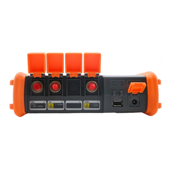
Installation Solution for the Bestselling Argentine Fiber Optic Endface Electric Cleaning Pen
Quick Clean cleaning tool 1. Depending on which kit you purchase, there are different types of Quick Clean cleaning tools included. Each is made with a proprietary lint-free cleaning strand to ensure you.
-
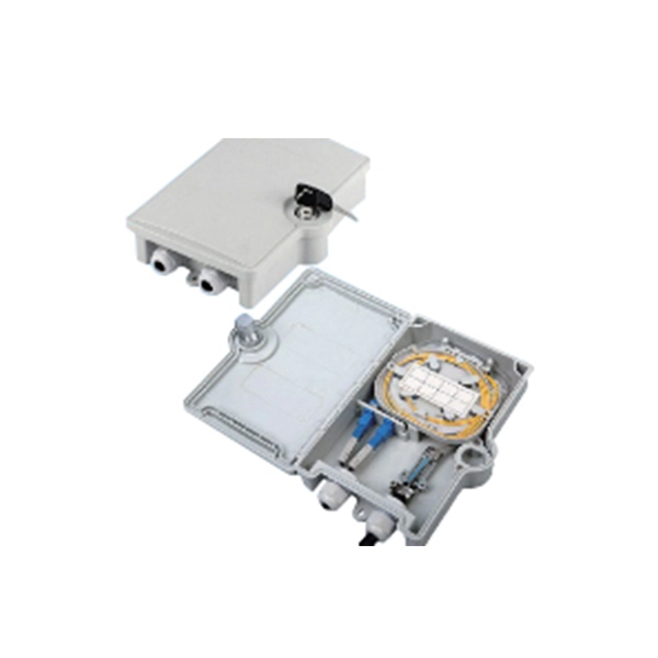
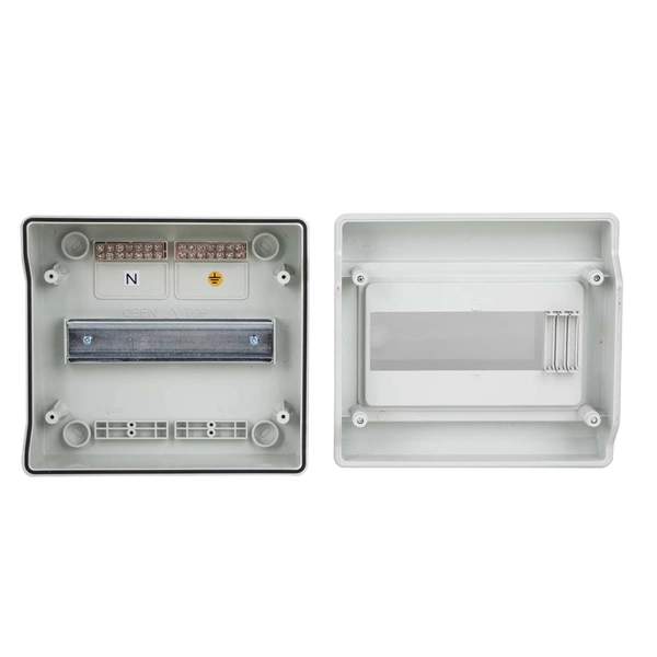
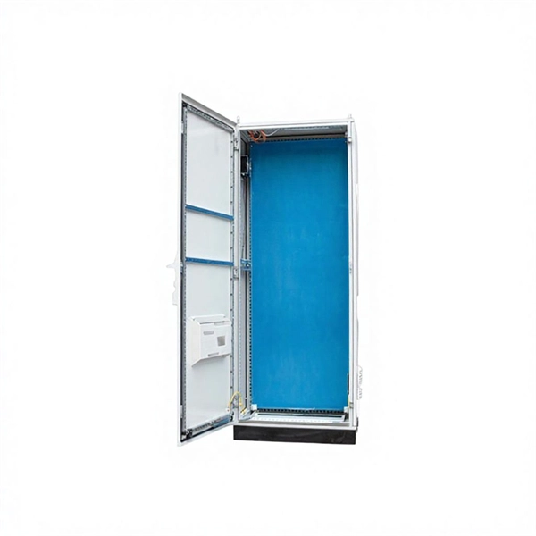
Installation of ordinary wiring in distribution boxes
What Is a Distribution Box?A distribution box, also known as a power distribution unit, is a critical component in any electrical system. It is the control center fo.
-
Installation steps for plastic cable trays
Step-1: Confirm the actual layout, dimensions & mounting height of cable trays & conduits. Step-3: Coordinate with other trades to prevent interference during installation. This guide breaks down the process step by step. Mark the cable tray route based on your electrical cable tray design and site. Article Summary: A compliant cable tray installation requires a thorough understanding of NEC Article 392, proper structural support, and precise installation techniques. In order to get it right, installers are supposed to adhere to a plan that ensures that wires are kept cool and the building is stable. The beginning of success is to review the Bill of Quantities (BOQ) so that. This method statement describes a detailed procedure for properly installing cable trays and conduits for the Feeder System. It ensures that all installation activities follow authorized plans, specifications, and standards.
[PDF Version]
-
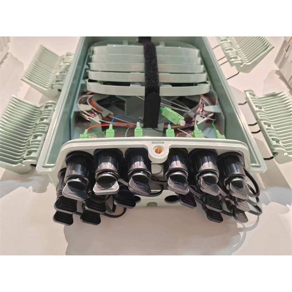
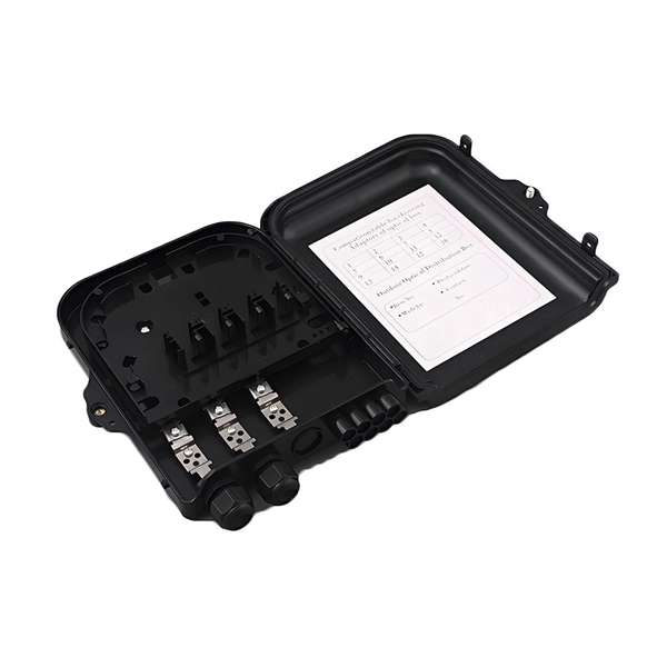
Fiber Optic Splice Installation and Removal Method
In this guide, we'll walk you through the entire process of preparing fiber optic cable for splicing and termination to fiber connectors. We'll explore the necessary tools, safety precautions, and step-by-step procedures for cable connectors, mechanical and fusion. A fiber optic cable splice is the process of permanently joining two fiber optic cables to create a continuous light path—vital when cables are cut, damaged, or need extending. This blog gets into the intricacies of these components, offering insights into their types, installation processes, maintenance, and more. What. What is Splicing and When Would You Want to Splice Fiber Optic Cables? First, let us understand the meaning of the term “splice. They protect and organize the sensitive connection points between optical fibres and play a decisive role in the quality, reliability and ease of maintenance of the entire network.
[PDF Version]
-

Cost of Vertical Installation of Optical Cable
The cost to install fiber optic cable ranges from $1. 50 to $42 per foot, with installation costs accounting for 60-80% of total project expenses. According to the Fiber Broadband Association's 2025 report, median costs are $8 per foot for aerial builds and $18 per foot for. Fiber-optic cable pricing depends on whether you're purchasing materials alone or including complete installation. The main cost drivers include material type, run length, trenching or aerial work, and any required permits or inspections. This breakdown gives you real numbers to build better estimates. We'll show actual costs for.
-
Installation method of arc-shaped distribution box
Install arc leaching chambers in adjacent rows to cover desired area. Ends of rows may be connected with piping to improve. This document is the 907B Arc 24 Cluster Installation Detail. A detail with descriptions and notes is included. The detail shows the ADS sewer and drain and/or ADS triplewall OR per local regulations, the distribution box and 6” minimum. Smooth. Whether you are an electrical contractor or a construction brigade, knowing how to properly and safely install distribution boxes is the basis of ensuring the safe operation of the entire system. This article details the process of installing them, which helps you comprehend distribution boxes. The Eaton 5/15 kV type VacClad-W arc resistant metal-clad switch-gear indoor housing assembly provides centralized control and protection of medium voltage power equipment and circuits in industrial, commercial, and utility installations involving genera-tors, motors, and feeder circuits.
[PDF Version]
-
Power Cable Tray Installation Steps
Step-1: Confirm the actual layout, dimensions & mounting height of cable trays & conduits. Step-3: Coordinate with other trades to prevent interference during installation. Article Summary: A compliant cable tray installation requires a thorough understanding of NEC Article 392, proper structural support, and precise installation techniques. The Cable Tray ng standards, performance standards, test standards and application in this document have been tested extens ompetent professional en completely installed, without damage either to conductors or. Here is a step-by-step guide on how to install a standard metal cable tray system (e. This guide covers copper and aluminum conductors from No. 14 AWG though 1000 kcmil, insulated for operation from 600 volts though 35 kilovolts.