-
What are the modules in a photovoltaic power generation device
Solar panels, technically called photovoltaic modules, are the most visible component of any PV system. These devices convert sunlight directly into electricity through the photovoltaic effect, where photons knock electrons loose from silicon atoms to create electrical current. Understanding the essential components that make up these systems is crucial for anyone considering solar installation, whether for residential, commercial, or utility-scale. Photovoltaic cells are connected electrically in series and/or parallel circuits to produce higher voltages, currents and power levels. A photovoltaic system, also called a PV system or solar power system, is an electric power system designed to supply usable solar power by means of photovoltaics. Battery Role: Batteries store solar energy to ensure a consistent power supply, even when sunlight is not available.
[PDF Version]
-
Does an optical power meter need to be calibrated after purchase
All test equipment must be calibrated on an annual basis. Calibration ensures that the test results you are measuring are indeed accurate. EXFO can help save both time and costs with an automated calibration test system that is designed for the verification of power meters, attenuators, sources and optical time-domain reflectometers (OTDRs). This application note demystifies how EXFO's IQS-12002 Optical Calibration System can guide. Below are general answers on how to operate, maintain, and calibrate an optical fiber ranger from the list of GAO Tek's optical power meters. Power On: Ensure the device is charged or properly connected to a power source. Select. n light source as shown below. Next press and hold the Mode Button until you hear a short. A send"'optical power meter is correctly calibrated when using a equivalent testing practices. For RF sensors, address mismatch uncertainty; for optical.
[PDF Version]
-
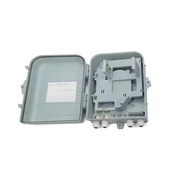
How about power communication optical cables
Power over Fiber (PoF) involves transmitting electrical power using optical fibers. CommScope solves these challenges with a complete range of powered fiber solutions designed for just the kind of high-demand powered devices that power smart networks in healthcare, hospitality, education, transportation and government environments, among others. That conversion can be done with a photovoltaic cell. A: OPGW (Optical Ground Wire) is a power transmission cable featuring dual functions on overhead lines. The power line protects (in lightning strikes) and the fiber for high-speed data communications. Widely used in overhead transmission lines, OPGW plays a crucial role in modern smart grids, telecom integration, and utility infrastructure. Utilities build fiber optic. This composite cable combines the distance and bandwidth capabilities of singlemode fiber with the power-carrying capability of 14-AWG copper conductors. by Jeanna Deese and Chris Rivas Power over Ethernet—it may be an old concept, but new applications continue to be identified that are redefining.
[PDF Version]
-
What does hi mean in optical power meter
4% or higher, the reader will read “HI”. com for more information or call (844) 829-3335 to talk to a professional. When a device displays "HI" on a meter, it almost always signifies a reading that is higher than the meter can measure, which can indicate a critical health concern requiring immediate attention. What does HI/LO mean when it appears after users scan the FreeStyle Libre 2 reader over the sensor? If LO appears on the. This manual contains 'WARNINGS” and 'ATTENTION” labels in this form, to indicate danger for persons or possible damage to equip-ment. The PM100D Handheld Optical Power and Energy Meter is. The KI 2600-H6 is a specialist very-high-power fiber optic power meter to test power, loss and continuity on single mode fiber optic systems up to +33 dBm / 2 Watts. The detector uses an innovative attenuator device for improved overall test accuracy. Power stability testing can be performed using the max/min recording function. The display can. The Optical Sensor Switch Hi-Lo is a non-invasive means for detection of a HI or LOW fl ow.
[PDF Version]
-
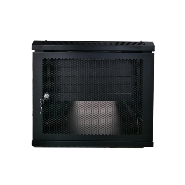
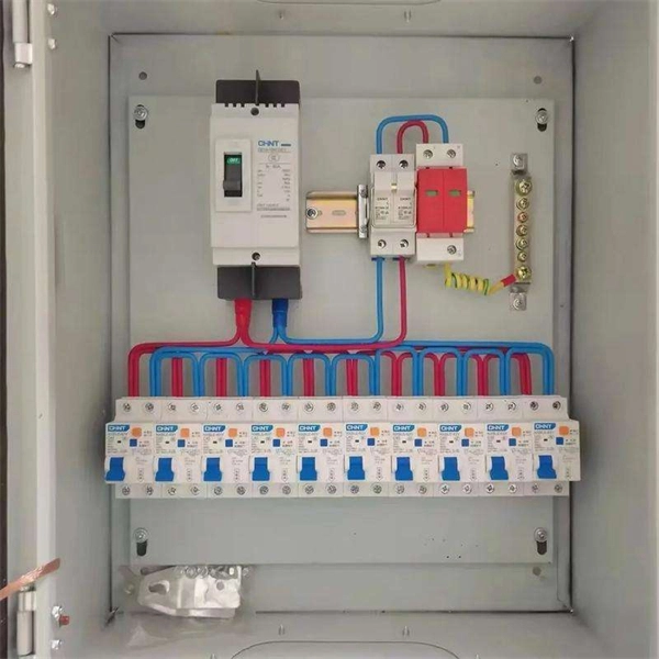
Power is connected inside the distribution box
Once inside the box, the incoming power is connected to bus bars, which are metal strips that conduct electricity. The bus bars distribute power to each circuit breaker. Depending on the system design, the electricity is regulated to usable voltage levels, such as 120V or 240V. Key components include circuit breakers, fuses, bus bars, and internal wiring for safety and. A power distribution box (also known as a distribution board or panel) is an essential electrical device that receives power from the main source and distributes it to various circuits throughout a facility. Each rack must safely deliver stable electrical power to dozens of servers, switches, and storage devices while maintaining reliability, airflow efficiency, and electrical safety.
-
Can fiber optic cables be run alongside 35kV power cables
General Consideration: It is generally not recommended to run fiber optic cables in the same conduit as electrical power cables. This is due to several potential risks and complications that can arise from such an arrangement. When a communications cable runs parallel and in close proximity to a power cable, these magnetic fields induce unwanted currents—a phenomenon known as inductive coupling—into the sensitive data conductors. This induced noise can. TECHNICAL GUIDELINE July 30, 2020 TG030 Rev. Electrical Interference: Electrical cables can produce electromagnetic. Maintaining proper separation between power, data, and limited energy cabling is foundational to system performance, safety, and code compliance. Other than that you haven't provided much information, given. Laying network cables parallel to electrical cables is often necessary due to space constraints but comes with its own set of challenges, primarily due to electromagnetic interference (EMI).
[PDF Version]
-
How to pull up a power fiber optic cable
Fiber optic cables should always be pulled by the strengthened yarn fibers inside the outer jacket. This article explores recommendations for pulling and installing fiber optic cable. Most fiber optic cables boast a pull strength of 100 – 200. Fiber optic cable is surprisingly strong, durable and pliable; however, several best practices should be followed to ensure a successful cable installation. Most fiber damage does not come from normal operation after the system is live. More than half of cable problems happen because of wrong pulling. In 2025, new tools like hydraulic blowers, smart monitors, and better grips help you lower risks, save money, and keep the. A duct is available from point A to point B, a pull tape is blown in, a fiber optic cable is attached to it and the cable is pulled through the duct.
-
How to route large power cable trays
Learn how to install cable trays for large-scale projects with our professional, step-by-step guide covering industry standards, safety protocols, and efficient routing techniques. This guide covers the critical steps, from selecting the right electrical cable tray and performing accurate cable fill. Cable tray installation implies the construction of an electric road that will be safe. The beginning of success is to review the Bill of Quantities (BOQ) so that. Cable tray systems provide a safe, organized, and flexible method for supporting insulated conductors and cables in commercial and industrial electrical installations.