-
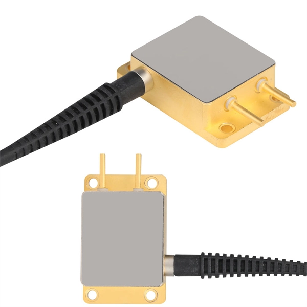
Fiber Bragg grating bending radius
The change of both physical length and strain-dependent refractive index of the fiber, are calculated by altering the bend radius of the sensor. In this example, a bend sensor based on fiber Bragg grating (FBG) is demonstrated. We observed a high resolution of the sensor at a level of 3. Their simplicity of operation coupled with attractive and unique features, such as all-fiber construction. A variation of the period of the grating inscripted in a fiber optic – induced by mechanical or thermal perturbation – causes a shift of the reflected peak wavelength, due to the related optical path length variation.
-
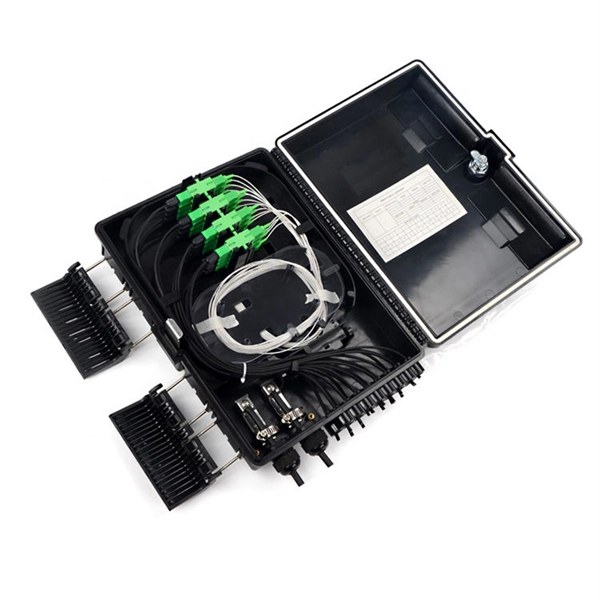
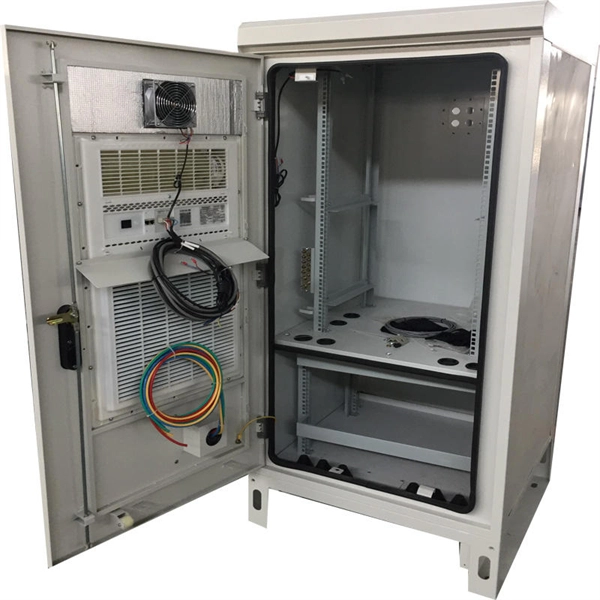
Bending radius of optical cable entering the equipment room
During the installation process, maintain a minimum bend radius of 20 times the cable diameter under tension, and 10 times after installation. Ignoring these rules leads to improper installation, signal loss, and costly cable damage. Fiber optic cable bend radius is a critical mechanical parameter that determines how sharply a cable can be bent without risking microbending, macrobending, signal loss, or long-term structural fatigue. Exceed it once and you might get away with it. Exceed it repeatedly, around truss corners, over stage decks, wound tight on undersized reels, and you're stacking up loss that. ter the cable has been placed in the raceway. Simply put, it is: how small the cable is allowed to bend but not being damaged.
-
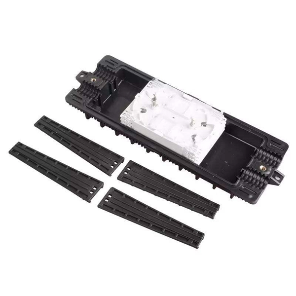
Bending radius of optical cable laying in ducts
The normal recommendation for fiber optic cable is the minimum bend radius under tension during pulling is 20 times the diameter of the cable (d). Damage may not always be obvious, like a kink in the cable, but may include broken fibers, fibers with higher loss due to stress and cable structural damage that may lead to reliability problems. What. The correct bend radius calculation is a fundamental prerequisite for high-quality fiber optic installations and is decisive for long-term network performance and reliability.
-
Minimum Ampere Capacity for a Secondary Distribution Box
This revision released concurrently with Standards and Equipment Advisory Information Bulletin 2024-014 Revised ES54 S1-01 Secondary Single-Phase Services 200 A Single and 400 A Multiple Self-Contained Meter Installation. This document shows the methods and requirements for installing PG&E-owned, underground service cables in customer-owned, residential, terminating facilities. REFERENCES This. talled today include 100 Amps (A) and 200A. The meter socket, which provides connection t considerations impacting electrical upgrade requirements and related costs. Electrical distribution diagrams can help you see how things are connected. Diagrams act like a map for your electrical system. NEC Article 408 covers switchboards, switchgear, and Panelboards installation and applications.
-
Calculation of cable tray bending dimensions
Click "Calculate" to see the minimum bending radius and the recommended standard tray bend radius (300mm to 900mm) required for safe installation. Tray bend radius must be ≥ minimum cable bend radius. Use the largest cable diameter in the tray for calculation. Always select the next higher standard. Cable tray sizing looks simple on paper, but in real projects it affects cable safety, thermal performance, maintainability, future expansion, and inspection approval. In EPC and industrial automation projects, a tray that is undersized forces last-minute redesigns, cable overcrowding, poor heat. Calculating an offset doesn't have to be a complex geometry lesson. Is the perpendicular distance measured from inside of side member (rail) web to opposite side member web.
-
Standards for bending distribution boxes
NEC Article 312 is all about cabinets, cutout boxes and meter socket enclosures and provides specific measurements to ensure conductors can be properly deflected within the enclosures. Code Change Summary: Revised code language now addresses deflection of conductors (wire-bending space) in meter socket enclosures. The NEC provides sizing requirements in 314. Keep in mind these. PVC conduits is not allowed. All sweeps shall be m de with manufactured elbows. If depth of landscaping material is not known at time of J-box installation, top of box base shall be 4" above surrounding dirt to al 0� This section describes general provisions, products and methods of execution relating to pull and junction boxes approved for use at ANC. Pull and junction boxes 50 cubic. An outdoor electrical distribution box serves as the critical junction point where incoming power lines are split into multiple branch circuits for outdoor installations, parking lots, building exteriors, and industrial facilities. All equipment must be supported directly by structural members with adequate load-bearing capacity and material integrity using appropriate anchoring/connection hardware.
[PDF Version]