-
Requirements for Cable Trench and Cable Tray Installation
This article provides a comprehensive framework that governs various aspects of cable tray installations, including the types of cables that are deemed acceptable for use, requirements for grounding and bonding, and stipulations regarding tray fill capacity. Additionally, it addresses critical. NEC Article 392 outlines the key rules for installing and maintaining industrial cable tray systems. These systems, made from metal or plastic, are open structures designed to support electrical conductors, ensuring proper organization and safety. This installation is for underground services from 2001 amps to 4000 amps. The following pages address the 2014 National Electrical Code® requirements for cable tray systems as well as design. Cable tray systems provide a safe, organized, and flexible method for supporting insulated conductors and cables in commercial and industrial electrical installations.
[PDF Version]
-
Installation Standards for Cable Tray Jumpers
NEMA Standards Publication VE 2-2018 Cable Tray Installation Guidelines Endorsed by Cable Tray Institute www. com Published by: National Electrical Manufacturers Association 1300 North 17th Street, Suite 900 Rosslyn, Virginia 22209 www. org © 2020 National. The intent of this article is to review grounding practices for cable tray wiring systems. The Equipment Grounding Conductor is the electrical circuit's safety conductor. MAN-3 Why Cable Tray? Safety. These systems provide an efficient and adaptable solution for managing a wide range of cables, including power cables, control cables, Ethernet, and fiber optic lines. The flexibility and scalability of cable trays make them an ideal choice for environments where cable density and organization can. Snap Track requires only single bonding jumper. Install Bonding Jumpers by bolting each lug to a 5/16 square hole. Standard splice plates can often provide a safe electrical path if they are UL Classified and bolted tight.
[PDF Version]
-
Power Cable Tray Installation Steps
Step-1: Confirm the actual layout, dimensions & mounting height of cable trays & conduits. Step-3: Coordinate with other trades to prevent interference during installation. Article Summary: A compliant cable tray installation requires a thorough understanding of NEC Article 392, proper structural support, and precise installation techniques. The Cable Tray ng standards, performance standards, test standards and application in this document have been tested extens ompetent professional en completely installed, without damage either to conductors or. Here is a step-by-step guide on how to install a standard metal cable tray system (e. This guide covers copper and aluminum conductors from No. 14 AWG though 1000 kcmil, insulated for operation from 600 volts though 35 kilovolts.
-
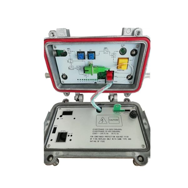
Installation method of cable tray in distribution box
Spring knot is used to connect cable tray or trunking to channel. Approved and correct fittings are used. Installed containments are free of damages. Whether you're building a commercial setup or upgrading an industrial plant, proper cable tray installation ensures neat wiring, safe access, and easy maintenance. But before you lay the first tray or clamp down a single cable, you need a solid plan. This guide breaks down the process step by step. This guide covers the critical steps, from selecting the right electrical cable tray and performing accurate cable fill. maintain spacing or to keep cables in place when the tray is ect the minimum bend ra-dius for cables as they exit the bottom of the cable tray. A rung spacing of 6 to 9 inches (150 to 230 mm) is preferable when the cable tray cont d for instrumentation and control applications that require. Below is the detailed cable tray installation method statement not only for cable tray but also applicable for GI ladder and trunking for indoor and outdoor applications and in service rooms like pump rooms, electrical rooms and plant rooms etc.
[PDF Version]
-
Cable tray installation includes fireproofing and sealing
Cable trays and busways at floor level or at slab penetrations shall have a waterstop no less than 50 mm in height. At slab penetrations, provide 20–30 mm of firestopping and install a fire-support plate at the top. Sealing shall be tight and reliable, without visible. FireResistant Solutions provides cable tray covering and fire-protection systems designed to safeguard electrical and data infrastructure in commercial and multifamily buildings. Route. Where cables pass through shafts, walls, slabs, or enter electrical panels or cabinets, openings shall be tightly sealed with firestopping materials in accordance with design requirements. This organic/inorganic elastomeric sheet is. SpecSeal Quick Clip Insulation Hangers are designed to accelerate the installation of curtain wall insulation for perimeter fire barrier systems. They provide robust support for cables while ensuring fire safety in extreme conditions.
[PDF Version]
-
Fireproof cable tray fire resistance duration
20 min that does not exceed 150 m2, and a peak smoke release rate that does not exceed 0. 3 ft2/sec) when tested using the FT4/IEEE 1202 flame test in either UL 1685 or UL 2556. Focuses on fire resistance, including burn duration and flame spread. Measures smoke, acid gas, and toxic gas emissions. International standard defining general fire performance requirements for cable trays. If your cable trays don't meet these standards, they could fail when exposed to fire. Must be listed as having adequate fire resistance and low-smoke producing characteristics by exhibiting a. The UL 1257 testing standard evaluates the performance of cable tray and conduit assemblies in a fire environment by subjecting them to various temperature conditions. Core Fire-Resistant Layer: The inner layer is wrapped with. Where cables pass through shafts, walls, slabs, or enter electrical panels or cabinets, openings shall be tightly sealed with firestopping materials in accordance with design requirements.
[PDF Version]