-
Cable tray layer marking
Every marking tells a story about how that cable is built, what environments it's rated for, and whether it can legally be used in the application your contractor is quoting. Let's break down a typical tray cable jacket marking: 12 AWG 3C TC-ER-JP SUN RES DIR BUR 600V 90C DRY / 75C. maintain spacing or to keep cables in place when the tray is ect the minimum bend ra-dius for cables as they exit the bottom of the cable tray. A rung spacing of 6 to 9 inches (150 to 230 mm) is preferable when the cable tray cont d for instrumentation and control applications that require. The B-Line series Cable Tray Manual was produced by our technical staff. We recognize the need for a complete cable tray reference source for electrical engineers and designers. UV-stabilized PVC is another widely used material, with special additives that help prevent discoloration, cracking and premature aging in sunlight. Need further customizations? Contact.
[PDF Version]
-
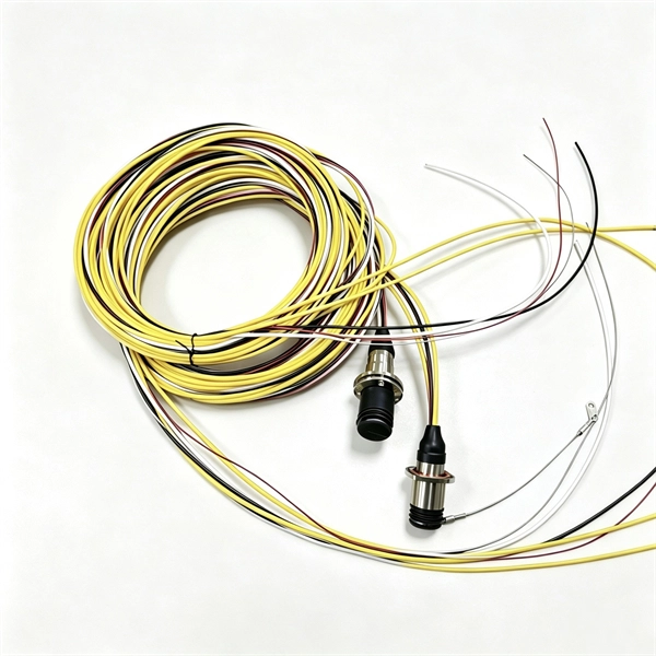
Single-mode port connected to multimode fiber optic cable
Single mode and multimode fiber cables are quite different when it comes to size, light source, signal, and so on. So, they definitely are not interchangeable, and compatibility issues can occur when you try to connect a single mode fiber optic connector to a multimode network. This is where fiber conversion comes in. Single-mode. To realize the short-range direct connection to the end B switch with the same port, the same 10GBASE-SR SFP+ module should be plugged into the end B switch port. What if end B is located in. It's possible because Multi-mode optical cables have a very wide fiber core – 62. Understanding the key differences between these two technologies is essential for IT professionals, business owners, and even homeowners looking to future-proof their network.
-
Translate the cable tray by 45 degrees
To create a 45-degree bend, cut the side rails to remove a segment calculated by the formula (Tan (22. Google's service, offered free of charge, instantly translates words, phrases, and web pages between English and over 100 other languages. So basically from my middle line what size to mark either side to cut my lip away to create different angles. Calculate horizontal, vertical, or compound cable tray offsets based on bend angle, offset distance, and available installation space. Measure this distance along the straight tray. ADVANCED S PRODUCTS I ASP 45° inuous system as well as stand-alone elements. 5∘ cuts on two separate pieces of cable tray. The second piece's cut must be in the opposite direction. Easy step to make 45 degree offset cable tray/Pipe and Air duct Cable tray 90 Degree Bend ! Cable tray ( Hindi) Cable tray 22. Distance of 145 mm ×.
[PDF Version]
-
What are the requirements for cable tray installation in factory buildings
Only approved tray-rated cables should be installed. Grounding and bonding are mandatory for metallic trays. Tray fill limits must be calculated properly. Mesh trays reduce installation time while. Cable tray systems provide a safe, organized, and flexible method for supporting insulated conductors and cables in commercial and industrial electrical installations. When properly selected and installed, cable trays simplify routing, improve accessibility, and support future expansion while. NEC Article 392 outlines the key rules for installing and maintaining industrial cable tray systems. These systems, made from metal or plastic, are open structures designed to support electrical conductors, ensuring proper organization and safety. 305(a)(3), or comparable standards promulgated by States operating OSHA-approved State plans. In addition, this document contains several references to provisions of the National Electric Code. The primary rulebook used in the safe use of cable trays is NEC Article 392.
[PDF Version]
-
Cable tray dip coating process
Steel trays get dipped in very hot molten zinc (around 450°C). The zinc bonds tightly to the steel, creating a thick, tough layer. Process: Degreasing → Pickling → Rinsing → Fluxing → Drying → Hot-dip galvanizing → Cooling → Passivation (optional) → Inspection. Hot-dip galvanizing is a process that enhances the durability of cable trays by creating a protective zinc coating, safeguarding them from corrosion. It is cost-effective, protects against a wide variety of environmental chemicals, and is self-healing if an area becomes unprotected through cuts or scratches. Steel is coated with zinc through electrolysis by dipping steel into a bath of. Legrand's offer of global solutions for wiremesh cable trays (and accessories) is one of the most complete on the market. It offers true freedom by allowing multiple configurations in a wide choice of finishes for optimal integration into any environment.
[PDF Version]
-
Optical cable channels are divided into
The light signal is divided into multiple channels with different frequencies and wavelengths, each transmitting a different data stream. In general, the fiber cable link system will be more secure if the fewer fiber cable segments. This region occupies a bandwidth of 95nm or 11THz! 8 cn cor where L is the fiber length, c is the speed of light, and ncor and nclad are the core and cladding refracitve indexes, respectively. Why not always use SMF? Optical phase information is lost in the detection process. What is a wavelength? What are optical wavelengths? What are nominal. In telecommunications, frequency-division multiplexing (FDM) is a technique by which the total bandwidth available in a communication medium is divided into a series of non-overlapping frequency bands, each of which is used to carry a separate signal. It essentially consists of a data transmitter, a transmission fiber (in some cases with built-in fiber amplifiers), and.
[PDF Version]
-
Fiber optic cable connected to router then connected to switch
If using a network switch with SFP ports, insert the fiber optic transceiver into the SFP port and connect the fiber optic cable to the transceiver. Connect the other end of the Ethernet cable to your network device, such as a computer, router, or. Fiber Optic Transceiver: Often used with media converters or network switches, these devices convert electrical signals to optical signals and vice versa. Patch Panel. As we speak I just have optic fibre (Community Fibre) connected to my Huawei modem / Linksys Velop which will be connected to a new POE switch (need to identify the best model to be compatible with my optic fibre extension project). Network topology refers to the way in which the links and nodes of a network are arranged in relation to each other. Use a standard Ethernet cable (Cat5e/Cat6) to.
[PDF Version]
-
How to pull up a power fiber optic cable
Fiber optic cables should always be pulled by the strengthened yarn fibers inside the outer jacket. This article explores recommendations for pulling and installing fiber optic cable. Most fiber optic cables boast a pull strength of 100 – 200. Fiber optic cable is surprisingly strong, durable and pliable; however, several best practices should be followed to ensure a successful cable installation. Most fiber damage does not come from normal operation after the system is live. More than half of cable problems happen because of wrong pulling. In 2025, new tools like hydraulic blowers, smart monitors, and better grips help you lower risks, save money, and keep the. A duct is available from point A to point B, a pull tape is blown in, a fiber optic cable is attached to it and the cable is pulled through the duct.
-
Typical installation height of indoor cable trays
The 2026 NEC introduced an important update: cable trays must have at least 12 inches of clear vertical space above them to allow for installation and maintenance access. Article Summary: A compliant cable tray installation requires a thorough understanding of NEC Article 392, proper structural support, and precise installation techniques. This guide covers the critical steps, from selecting the right electrical cable tray and performing accurate cable fill. We recognize the need for a complete cable tray reference source for electrical engineers and designers. Trays and fittings should be stacked by their physical dimensions (width) and type. us-trations without notice. All illustrations, descriptions and technical information included in this document are provided as indications and can cable trays are equivalent. Wire Mesh Cable Trays A job site, field adaptable support system primarily for.
[PDF Version]