-
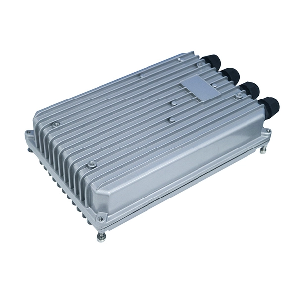
Is the optical module for using a microscope
The optical parts of the microscope are used to view, magnify, and produce an image from a specimen placed on a slide. These parts include: 1. Eyepiece – The eyepiece (ocular Lens) is closest to the viewer's.
-
How to switch screens using the ReionalKVM switcher
Press the hotkey to switch between computers in full screen mode, or to switch the keyboard and mouse between computers in PIP or PBP modes. This article and video walk you through everything you need to set up a dual monitor KVM switch the right way—without guesswork or frustration. Is This the Right Setup for You? This article has been fully. A KVM (Keyboard, Video, Mouse) switch is an essential tool for anyone juggling multiple devices or systems while wanting the convenience of using just one keyboard, monitor, and mouse setup. 1 Front. How does my Dual Head KVM work? 3. How do I replace the F1DG102W wireless remote control? 4. us/081-HKU0202 Today's step-by-step KVM switcher setup video shows you how to connect 2 laptops with 2 shared screens.
-
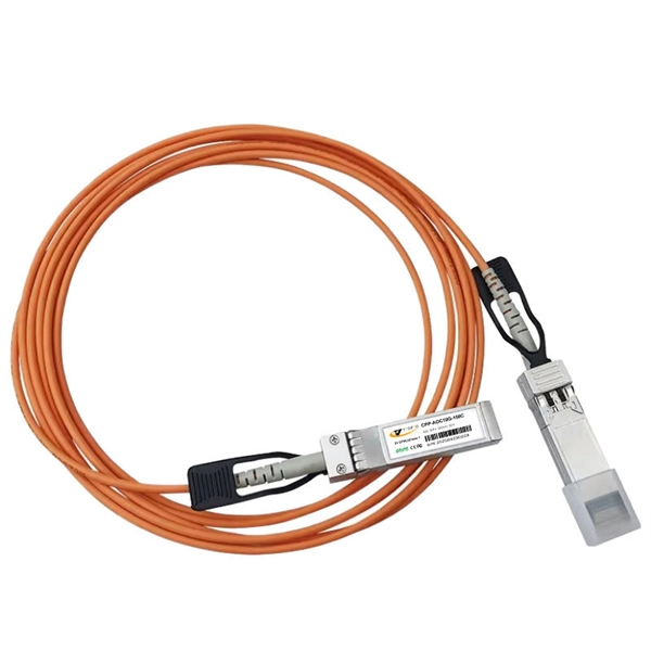
When using wavelength division multiplexing technology
Wavelength Division Multiplexing (WDM) stands out as a cornerstone, enabling multiple data streams to travel simultaneously over a single fiber. This guide delves into the principles, types, applications, and future trends of WDM. Tailored for professionals sourcing solutions from CommMesh, it. Explore the fundamentals of Wavelength Division Multiplexing (WDM), its types, benefits, challenges, and future prospects in our detailed guide. With the endless upgrades and improvements, WDM technology is no longer just adopted by carriers and service providers, but also applied for. 📦 For purchasing, use the RP Photonics Buyer's Guide for wavelength division multiplexing. It provides an expert-curated supplier directory, buyer-focused technical background information, and structured selection criteria to support professional procurement decisions.
[PDF Version]
-
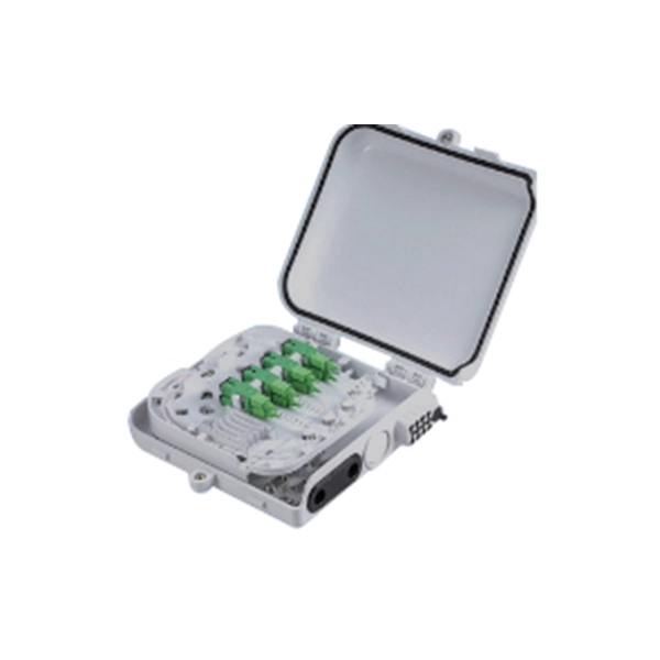
How to determine light attenuation of red light using an optical power meter
Optical attenuation compares input and output power on a logarithmic scale. When powers are in linear units, the loss in decibels is: Attenuation (dB) = 10 × log10 (Pin / Pout) If the link length L is provided, the attenuation coefficient is: Coefficient (dB/km) =. Analyze optical power drop across fibers and links. Switch units, lengths, and calculation modes easily. Needed when attenuation is an. Optical power, required for measuring source power, receiver power and, when used with a test source, loss or attenuation, is the most important parameter and is required for almost every fiber optic test. Backscatter and wavelength measurements are the next most important and bandwidth or. Optical power meters are a key element in the optimization and maintenance of such optical networks and of their components. But, for designers, just starting to work in the fiber-optic design space, measuring attenuation can seem like a monumental task.
[PDF Version]
-
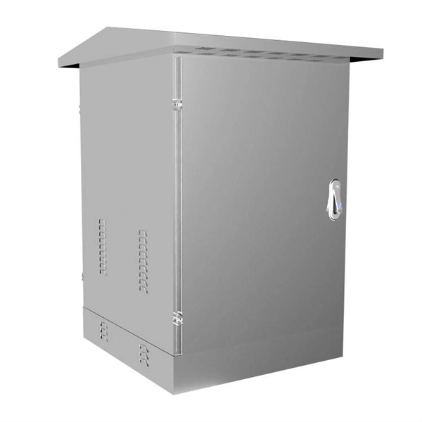
What should be noted when using cable trays
Grounding and bonding are mandatory for metallic trays. Tray fill limits must be calculated properly. This article explains the main requirements and good practices for cable tray systems, including tray types, materials, loading, supports, bonding, cable selection, and installation details. The content is written to be SEO-friendly and compatible with Yoast SEO for WordPress. Introduction and. en completely installed, without damage either to conductors or structural system use maintain spacing or to keep cables in place when the tray is ect the minimum bend ra-dius for cables as they exit the bottom of the cable tray. A rung spacing of 6 to 9 inches (150 to 230 mm) is preferable when. What is the most common cause of cable failure? What is the most common cable management solution? What are the potential problems with cables? Any modern industrial, commercial, or data-intensive environment is mostly composed of effective cable management. A well-considered cable management. Related Articles: What Are The Common Types of Cable Trays 4. You should consider it as a series of instructions that make the buildings resistant to.
[PDF Version]