-
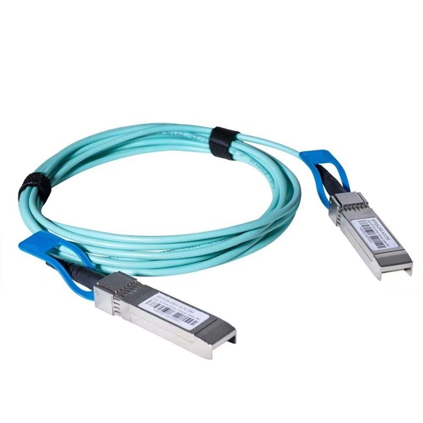
Impact force of optical cables
This procedure provides a method to determine the ability of optical fiber cables to withstand impact loads. (b) Damage to the outer sheath. Laboratory accelerated aging environments have long been used as a measure to predict field performance of optical fiber and cables'. Fiber optic impact testing is a used to assess the resilience and durability of fiber optic cables when subjected to impact or mechanical stress. It involves subjecting the cable to various impacts or mechanical forces to evaluate its ability to withstand such events without experiencing. Fiber design and transmission technology have collaboratively evolved to increase bandwidth. Although there is an. For fiber optic cable, the tensile strength of a cable represents the highest load or pulling force that can be placed upon any cable before any damage occurs to the fibers or their optical properties and characteristics. This is not the cable breaking strength, but a realistic allowable limit. We describe how this reliability relates with the various processing steps before the cable is eventually put into service - e.
[PDF Version]
-
Experimental Report on Ceramic Fuse Pull-out Force Measurement
This paper identifies failure mechanisms of axial lead fuses subjected to real field ambient thermal profiles by finite element simulations and experimental testing. Experimental observation of failed fuses attribute.
-
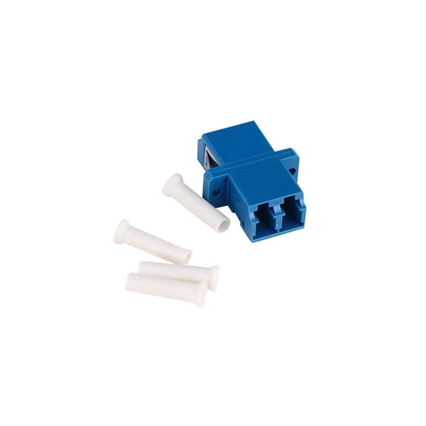
Find the air interface with the beam splitter
A beam splitter or beamsplitter is an optical device that splits a beam of light into a transmitted and a reflected beam. It is a crucial part of many optical experimental and measurement systems, such as interferometers, also finding widespread application in fibre optic telecommunications. DesignsIn its most common form, a cube, a beam splitter is made from two triangular glass which are glued together at their base using polyester,, or urethane-based adhesives. (Before these synthetic,. Beam splitters are sometimes used to recombine beams of light, as in a. In this case there are two incoming beams, and potentially two outgoing beams. But the amplitudes.
-
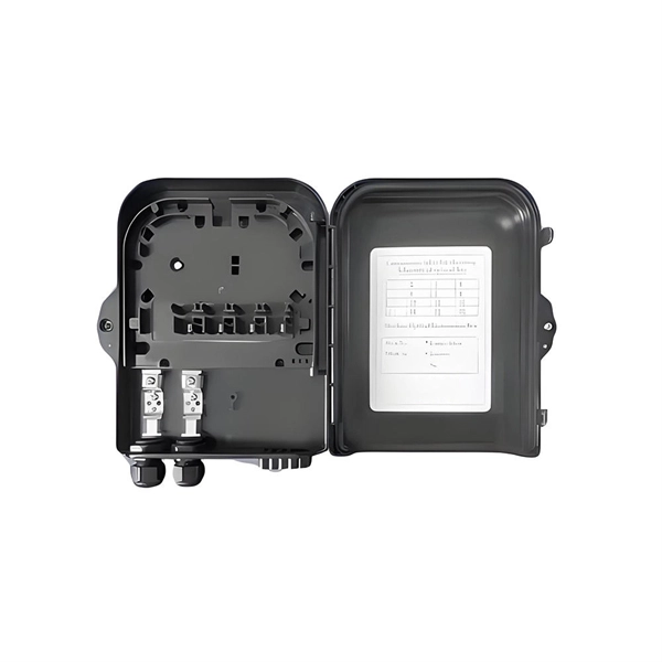
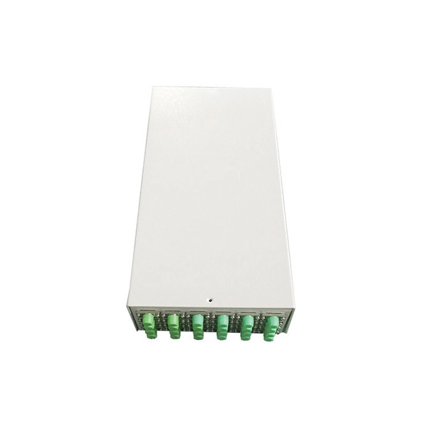
Spacing of the side of the distribution box
Side clearance: There should be a minimum of 30 inches of clearance from the sides of all electrical equipment, but in no case less than the width of the equipment itself. This is referred to as the side-to-side working space. In industrial power distribution systems, cable distribution boxes (also known as power distributor boxes, distribution electrical boxes, or electrical power distribution boxes) are the core hub of power transmission, branching, and protection. Its layout directly affects the efficiency of the. NEC Article 314 establishes requirements for the installation and use of electrical boxes, conduit bodies, fittings, and handhole enclosures. NEC Article 408. Boxes distribute low currents in an area equipped with 1 to 12 RJ 45 sockets. They centralise connections to ensure flexibility and that the installation is up to date.
[PDF Version]
-
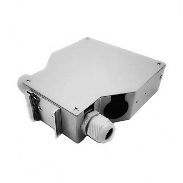
The power cable enters from the bottom of the distribution box
Cables can enter the structure from the floor (bottom entry) or from above (top entry. ) Distribution structures divide and send power to branch circuit protection devices and then to branch circuits to power downstream loads. Power. When installing a new overhead combination service for a residential service replacement we were told by the EI that we could not install our romex cables coming from under the house in a single 2" pipe approx. The scope of the article includes electrical requirements related to: Below is a complete overview. Once the box is securely in place, it's time to bring in the cables that will carry current from the main panel. Escape will cancel and close the window. Power from the utility company is typically delivered through three large conductors, which may enter the house overhead or underground. Overhead service. Fixed to a wall—This is a common approach for small electrical distribution boards. For bottom entry, the floor can incorporate a trench or false floor, which is often simpler since it provides.
[PDF Version]
-
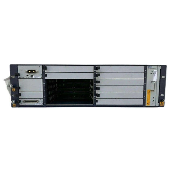
Should the cable management rack be installed in the front or the back
Leave space for cable management —especially in the back. Ensure front-to-back airflow by leaving gaps or using filler panels. This method helps maintain neatness and accessibility within the rack while ensuring efficient airflow and ease of maintenance. Both overhead and under floor pathways should be designed to support the weight of cables in the initial installation and it should also facilitate the addition of future cables. With proper design and structured tools, it helps organize cables, ensure stable signal transmission, simplify maintenance, and improve overall system. Here are some best practices for rack placement: Implementing hot and cold aisle containment is a fundamental strategy for improving airflow and cooling efficiency. The racks should be positioned in a way that optimizes.