-

Distance between primary and secondary power distribution boxes
A minimum of 24 inches of cover for secondary (0 − 750 V) electric service, or 30 inches minimum cover for primary (over 750 V) is required for electric trench only. Cover is the distance from the outer surface of an underground facility to the top of the final grade. Primary distribution systems consist of feeders that deliver power from distribution substations to distribution transformers. At this. nt, and/or other requirements. ” Strict adherence to ons for manholes are critical. At a. This document is published to provide specifications, information, and guidance to assist developers in planning for and obtaining proper and prompt electric facilities to serve underground developments in the FirstEnergy Service territory. The requirements detailed in this document address conduit.
-
Light collection power of the second-stage beam splitter
It is currently used in modern three-CCD cameras. An optically similar system is used in reverse as a beam-combiner in three- LCD projectors, in which light from three separate monochrome LCD displays is combined into a single full-color image for projection.OverviewA beam splitter or beamsplitter is an that splits a beam of into a transmitted and a reflected beam. It is a crucial part of many optical experimental and measurement systems, such as In its most common form, a cube, a beam splitter is made from two triangular glass which are glued together at their base using polyester,, or urethane-based adhesives. (Before these synthetic,. Beam splitters are sometimes used to recombine beams of light, as in a. In this case there are two incoming beams, and potentially two outgoing beams. But the amplitudes.
-
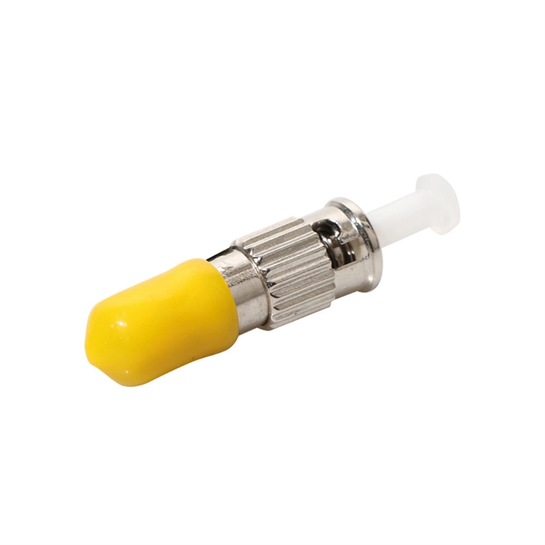
How are 36 cores of power optical fiber cable divided
Multi-core optical fiber is a breakthrough in optical networking that packs multiple cores into one fiber, enabling tremendous capacity gains via spatial division multiplexing. By carrying parallel channels in a single strand, MCF allows operators to multiply bandwidth without. These optical signals are transmitted (Tx) and received (Rx) at deliberate power levels expressed and measured in milliwatts (mW), an absolute optical power level. Absolute levels may also be represented as a relative optical power level, known decibel milliwatt or dBm. Its primary function is to split the optical signal of one input optical fiber into multiple optical signals and transmit them to. MTP/MPO cables are a class of high-density multi-core fiber optic connectivity solutions widely used in data centers and telecom networks, which are designed to achieve fast connection of multi-core fiber optics through a single interface. In contrast to conventional single-core fibers (one core on the fiber axis), MCF can have two or more.
[PDF Version]
-
Can fiber optic cables be run alongside 35kV power cables
General Consideration: It is generally not recommended to run fiber optic cables in the same conduit as electrical power cables. This is due to several potential risks and complications that can arise from such an arrangement. When a communications cable runs parallel and in close proximity to a power cable, these magnetic fields induce unwanted currents—a phenomenon known as inductive coupling—into the sensitive data conductors. This induced noise can. TECHNICAL GUIDELINE July 30, 2020 TG030 Rev. Electrical Interference: Electrical cables can produce electromagnetic. Maintaining proper separation between power, data, and limited energy cabling is foundational to system performance, safety, and code compliance. Other than that you haven't provided much information, given. Laying network cables parallel to electrical cables is often necessary due to space constraints but comes with its own set of challenges, primarily due to electromagnetic interference (EMI).
[PDF Version]
-
How are optical power meters classified
An optical power meter (OPM) is a device used to measure the power in an signal. The term usually refers to a device for testing average power in systems. Other general purpose light power measuring devices are usually called,, power meters (can be sensors or ), or lux meters. A typical optical power meter consists of a , measuring and display. The sens.