-
Cable tray installation includes fireproofing and sealing
Cable trays and busways at floor level or at slab penetrations shall have a waterstop no less than 50 mm in height. At slab penetrations, provide 20–30 mm of firestopping and install a fire-support plate at the top. Sealing shall be tight and reliable, without visible. FireResistant Solutions provides cable tray covering and fire-protection systems designed to safeguard electrical and data infrastructure in commercial and multifamily buildings. Route. Where cables pass through shafts, walls, slabs, or enter electrical panels or cabinets, openings shall be tightly sealed with firestopping materials in accordance with design requirements. This organic/inorganic elastomeric sheet is. SpecSeal Quick Clip Insulation Hangers are designed to accelerate the installation of curtain wall insulation for perimeter fire barrier systems. They provide robust support for cables while ensuring fire safety in extreme conditions.
[PDF Version]
-
Installation method of cable tray in distribution box
Spring knot is used to connect cable tray or trunking to channel. Approved and correct fittings are used. Installed containments are free of damages. Whether you're building a commercial setup or upgrading an industrial plant, proper cable tray installation ensures neat wiring, safe access, and easy maintenance. But before you lay the first tray or clamp down a single cable, you need a solid plan. This guide breaks down the process step by step. This guide covers the critical steps, from selecting the right electrical cable tray and performing accurate cable fill. maintain spacing or to keep cables in place when the tray is ect the minimum bend ra-dius for cables as they exit the bottom of the cable tray. A rung spacing of 6 to 9 inches (150 to 230 mm) is preferable when the cable tray cont d for instrumentation and control applications that require. Below is the detailed cable tray installation method statement not only for cable tray but also applicable for GI ladder and trunking for indoor and outdoor applications and in service rooms like pump rooms, electrical rooms and plant rooms etc.
[PDF Version]
-
Price of cable tray installation for storefronts
Cable tray pricing depends on materials, coatings, size, supplier margins, and order quantity —plus hidden costs like shipping and installation. Cable tray installation cost per meter varies by specifications; GangLong Fiberglass offers kits for raised floor system and facility needs. Cable trays are vital in electrical installations, providing secure pathways for power, communication, and control cables across residential, commercial, and. Cable tray pricing represents a crucial consideration in modern electrical infrastructure planning, encompassing various factors that influence the overall cost-effectiveness of cable management systems. We will figure all the cable tray components needed based on the total length you provide us. Choosing the right cable. Suppose that you require the installation of a new internet cable in your building.
[PDF Version]
-
Cable tray internal wiring installation
Proper planning for installing cable tray includes calculations based on loading, support systems, cable/wire fill and spacing, conductor types, securing of the cables and wire, and proper grounding and bonding are all important aspects of cable tray installation. NEMA VE2 addresses cable tray installation and provides information on maintenance and system modification. The following pages address the 2014 National Electrical Code® requirements for cable tray systems as well as design solutions from practical experience. headquartered manufacturer with over 130 years of supplying solutions for the electrical and data markets. Hubbell's strength is demonstrated by a long-standing reputation for supplying reliable. en completely installed, without damage either to conductors or structural system use maintain spacing or to keep cables in place when the tray is ect the minimum bend ra-dius for cables as they exit the bottom of the cable tray. A rung spacing of 6 to 9 inches (150 to 230 mm) is preferable when. How about organizing your wiring with a cable tray system? Smart move.
[PDF Version]
-
Power Cable Tray Installation Steps
Step-1: Confirm the actual layout, dimensions & mounting height of cable trays & conduits. Step-3: Coordinate with other trades to prevent interference during installation. Article Summary: A compliant cable tray installation requires a thorough understanding of NEC Article 392, proper structural support, and precise installation techniques. The Cable Tray ng standards, performance standards, test standards and application in this document have been tested extens ompetent professional en completely installed, without damage either to conductors or. Here is a step-by-step guide on how to install a standard metal cable tray system (e. This guide covers copper and aluminum conductors from No. 14 AWG though 1000 kcmil, insulated for operation from 600 volts though 35 kilovolts.
-
Requirements for Cable Trench and Cable Tray Installation
This article provides a comprehensive framework that governs various aspects of cable tray installations, including the types of cables that are deemed acceptable for use, requirements for grounding and bonding, and stipulations regarding tray fill capacity. Additionally, it addresses critical. NEC Article 392 outlines the key rules for installing and maintaining industrial cable tray systems. These systems, made from metal or plastic, are open structures designed to support electrical conductors, ensuring proper organization and safety. This installation is for underground services from 2001 amps to 4000 amps. The following pages address the 2014 National Electrical Code® requirements for cable tray systems as well as design. Cable tray systems provide a safe, organized, and flexible method for supporting insulated conductors and cables in commercial and industrial electrical installations.
[PDF Version]
-

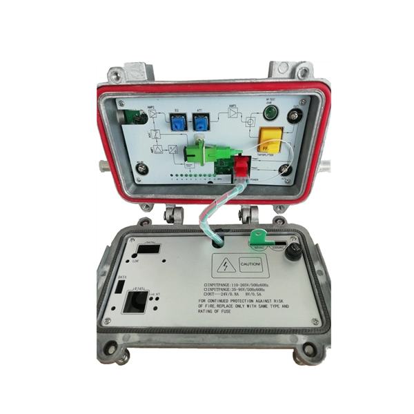
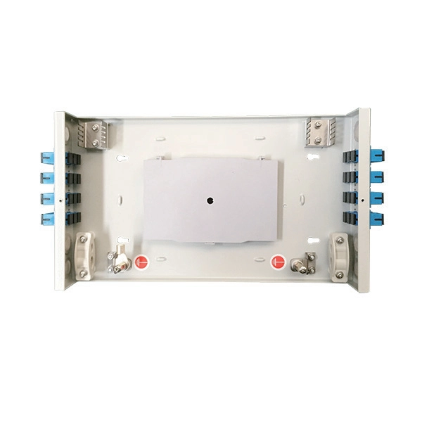
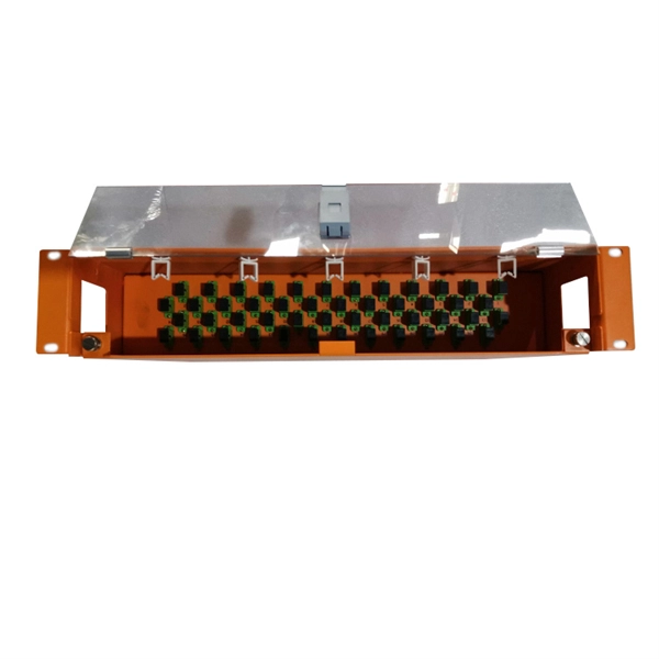
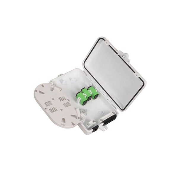
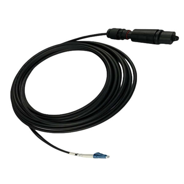
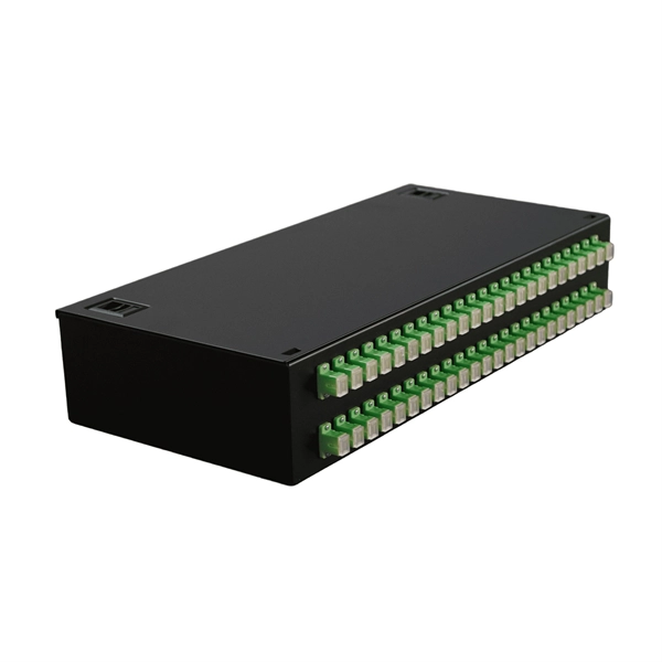
Installation of 48-core fiber optic cable junction box
OPGW cable joint box installation involves several key stages: selecting the appropriate location, preparing both the cable and the joint box, splicing fibers, and sealing the joint box properly. Adhering to these steps ensures optimal performance and longevity of the. The SJ-ODB-48-SMC 48 cores fiber optic termination box delivers robust, high-density cable management with IP65-rated durability and versatile installation for reliable FTTx network infrastructure. The FDB-48 is suitable for indoor or outdoor FTTX applications that support up to 48. The mini type dome fiber optic splice closure is suitable for fiber cable of 21mm and 34mm diameter. It can accommodate 48 fibers with 1 inlet and 3 outlet. Built with an IP65-rated enclosure, this terminal box is designed to withstand harsh environments, making it suitable. DUCT, PLEASE READ THESE INSTRUCTIONS CAREFU cal fiber cable splicing, joint and protection. It is waterproof and dust proof and suitable for outdoor aerial hanged, pole unted, wall mounted, duct, buried application.
[PDF Version]
-
How to determine the cable model in a cable tray
Choosing the right tray cable type — TC, TC-ER, VNTC, PLTC, or ITC — depends on the voltage class, environment, and NEC® article governing your installation. It is the standard wiring method for industrial plants, commercial buildings, and utility installations where cable trays provide accessible. Among the various cable types, tray cables are a preferred solution for robust, adaptable, code-compliant wiring. Whether you're an engineer, contractor, facilities manager or simply curious, this ultimate guide provides an in-depth understanding of tray cables, covering their types, standards. The cable jacket tells the story if you know how to read it. Manufacturers must print specific information on cable jackets per UL requirements, and understanding this code prevents most identification errors. The. Tray cable is a widely used type of multiconductor or multipair cable approved for installation in cable raceways and cable trays. In this technical guide, we'll explore all you.
[PDF Version]
-
What thickness of cable tray trough meets national standards
Another advantage of this method is coating thickness. 50 ounces per square foot on each side, or a total 3. All rights, including translation into other languages, reserved under the Universal Copyright Convention, the Berne Convention for the Protection of Literary and Artistic Works, and the International and Pan American copyright conventions. The information in this publication was considered. The national standard for cable tray thickness specifies the minimum allowable plate thickness for different The national standard for cable tray thickness specifies the minimum allowable plate thickness for different specifications of steel bridge, FRP bridge and aluminum alloy bridge. A rung spacing of 6 to 9 inches (150 to 230 mm) is preferable when the cable tray cont d for instrumentation and control applications that require. C C ble Trough e Height T e Height T h Heig e # Si 5 – 2. Level of Harmonization This standard uses an IEC format, but is not based on, nor is it to be considered equivalent to, an IEC standard.
[PDF Version]
-
No supports are allowed at the cable tray connection points
Support spacing for cable trays must align with the manufacturer's instructions, as outlined in NEC 392. Generally, standard trays require supports every 6 to 10 feet, while heavy-duty, long-span trays can handle distances of up to 20 feet between supports. This is a description of how to select, install, and support these metal or plastic frames, on which electrical wires are installed. Here's what you need to know: Cable Types: Only use. Cable trays can be part of a planned cable management system to support, route, protect, and provide a pathway for cable systems. Power, low voltage control, data, or telecommunications wiring distribution systems can be used with cable trays. Cable trays can provide a safe component of a power, low voltage.
-
Does the cable tray need to be weighed down
In vertical or angled tray runs, cables should be fastened to the tray's transverse members to keep them secure. In horizontal runs, the weight of the cables often keeps them in place, but adding ties can help maintain spacing, which improves heat dissipation. This guide covers the critical steps, from selecting the right electrical cable tray and performing accurate cable fill calculations to managing a safe cable pull through and ensuring all bonding and grounding requirements are met. Organization and routing – provide clear routes for power, control, and data cables and simplify cable management. Grounding and bonding are mandatory for metallic trays. Tray fill limits must be calculated properly. Here's what you need to know: Cable Types: Only use. Hubbell Take Off Support provides the contractor, engineer, end user a completed BOM, including all related products, counts, symbol legends and information required to price a project.
[PDF Version]
-
How to connect the main cable to the branch line of the cable tray
Place screw head on inside of branch cable tray, put the jumper outside of branch cable tray, add flat washer and locknut, then tighten. Cable tray shall be grounded as defined in SAES-P-111 Section 7, 8, and 9 and NEMA VE-2 Section 4. Connecting cable trays correctly is essential for system safety, load stability, and long-term performance. Choosing the right one depends on project conditions, load. All cable trays and supports will be installed as shown on EPC approved design construction drawings and located to avoid interferences with other facilities. NEMA ratings are standards that define the types of environments an electrical enclosure can be used in. It ensures that all installation activities follow authorized plans, specifications, and standards.