-
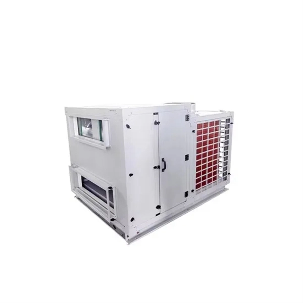
Server memory required for AI development
Your AI server CPU requirements: 4–16 vCPU (or more for parallel ETL), RAM sized at 2–3× the largest dataset in memory, and NVMe sustained read/write above your data loader rate. Modern AI work can be classified into four categories: Exploration and data preparation. This stage is heavily reliant on powerful processors, large memory, and swift NVMe setups, which is why the AI development server requirements here focus on balanced CPU cores and storage throughput. AI workloads differ fundamentally from traditional enterprise applications. Databases, web. AI hardware refers to the physical components and systems designed specifically to accelerate and optimize artificial intelligence workloads like machine learning (ML), deep learning, and neural network inference and training. Each of these components offers distinct. The CPU can also be the main compute engine when GPU limitations such as onboard memory (VRAM) availability require it. This is because both of these offer excellent.
[PDF Version]
-
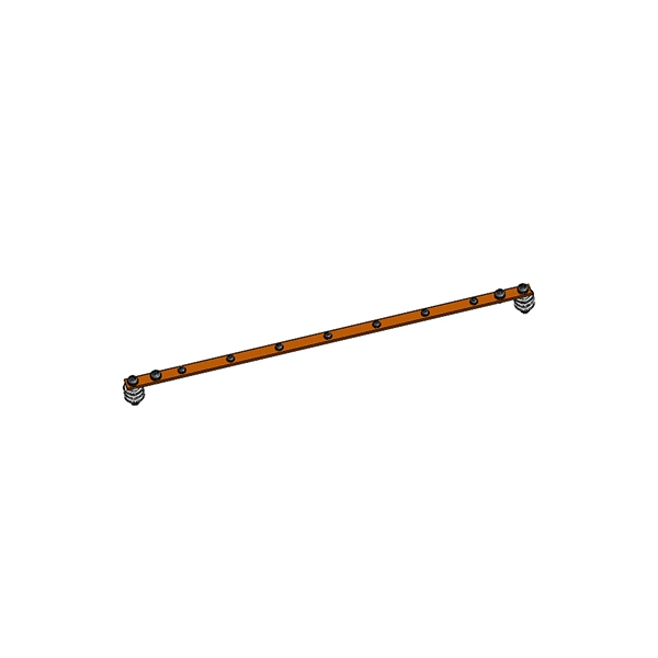
How to connect RRU optical modules in series
A fiber optic cable connects the RRU to the RBS main unit or an expanded macro RBS. The RRUs can be connected in a cascade configuration and a star configuration with optical cable links. User Guide About This Document About This Document Purpose This document describes the RRU hardware and provides instructions in hardware installation, cable connections, hardware installation check, and hardware maintenance. It also provides checklists as reference. In this document, eRRU3232 is used as an example. When wrapping the waterproofing tape, apply even force to extend the tape until the width of the tape is 1/2 of the original width. Start-up Below you will find brief information for RRU RFD01F Series.
-
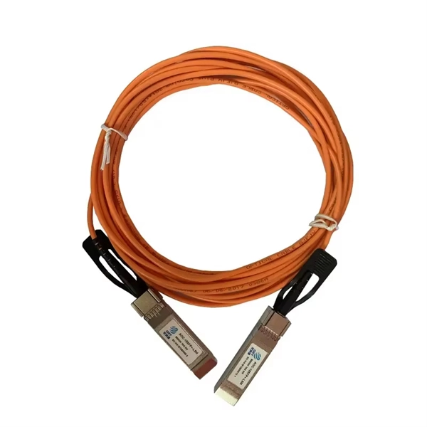
How to connect and splice optical cables in series
The simplest method: connect two cables pre-connectorized via a coupler (also called an adapter). The coupler aligns the two ferrules of the connectors using a zirconia sleeve. Before jumping into the physical steps, it's important to understand the two primary methods of fiber splicing: fusion splicing and. Fiber optic cable splicing involves joining two fiber optic cables together. Another method of connecting optical fibers is termination or connectorization, which consists of processing the end of a fiber optic bundle so that it can be connected to other fibers or devices through fiber optic. Connecting fiber optic cables requires precision and care due to the delicate nature of the fibers. At Turn-Key. Proper connection of fiber optic cables is essential to harness these benefits fully, as even minor errors can lead to significant performance issues like signal loss.
[PDF Version]
-
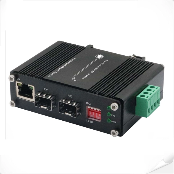
Huawei Optical Module Model Series List
Huawei S series devices support optical modules of the following encapsulation types: CFP, QSFP+, QSFP28, XFP, SFP, eSFP, and SFP+. All optical modules are hot swappable. Huawei's data center network leverages advanced optoelectronics technologies to establish high-performance connections, ensuring reliable interconnectivity across data center infrastructures. GE to 100GE full-scenario optical interconnection solutions for general-purpose computing. Together, they ensure resilient data center interconnectivity and empower. On an optical network, a sender needs to convert electrical signals into optical signals before sending them to a receiver, and the receiver needs to convert received optical signals into electrical signals. Huawei's main business scope is switching. ers, only the short transmission distance is supported. Whether optical attenuators need to be deployed at the receive end o If an optical module has been certified by Huawei, its label contains "HUAWEI", as shown in Figure 8-1. In the display elabel command output, the Manufactured field displays a date later than 2013-07-01.
[PDF Version]
-
The Development History of Fiber Optic Acoustic Sensors
Fiber-optic interferometric acoustic sensors were first proposed for US Navy applications 36 years ago. This paper will review the origin, development and deployment of these sensors. Future applications will also be discussed. This content is available for download via your institution's subscription. To access this item, please sign. Fiber‐optic sensor technology has experienced tremendous growth since its early beginnings in the 1970s with early laboratory demonstrations of fiber‐optic gyros and acoustic sensors and the introduction of the first commercial intensity and spectrally based sensors. These early efforts were. The Design Of Fiber Optic Sensors For Measuring Hydrodynamic. Navy's effort to develop sensors that used optical fiber to detect targets at sea offers a window into how a technology goes from basic research to production.
[PDF Version]
-
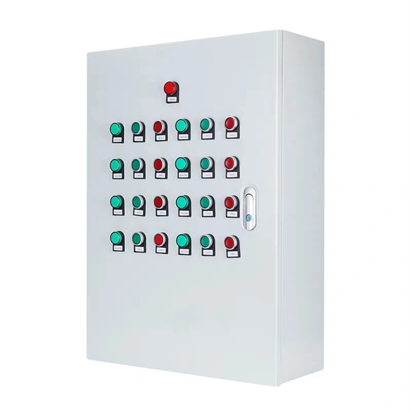
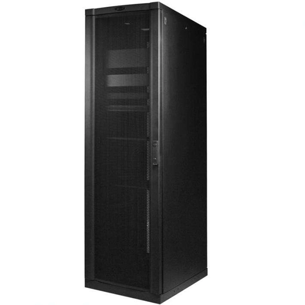
Future Development of Network Security Equipment
This article explores the emerging trends, technologies, and practices shaping network security services in 2025. Artificial intelligence (AI) is being increasingly used by cyber attackers to launch sophisticated and targeted attacks. These attacks can also adapt and evolve in real-time, making them. From the growing speed, scale and sophistication of cyberattacks to the changing nature of how we work and connect, the future of network security depends on a holistic approach that integrates advanced AI technologies and seamless user experience.
-
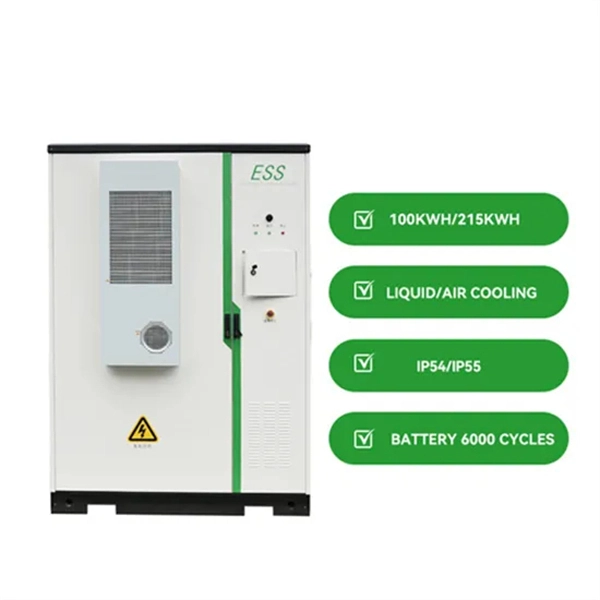
Energy Internet Development Positioning
This article deals with a thorough investigation of the energy internet towards future emerging technologies for energy distribution and management to solve existing limitations and enhance the performanc.
-
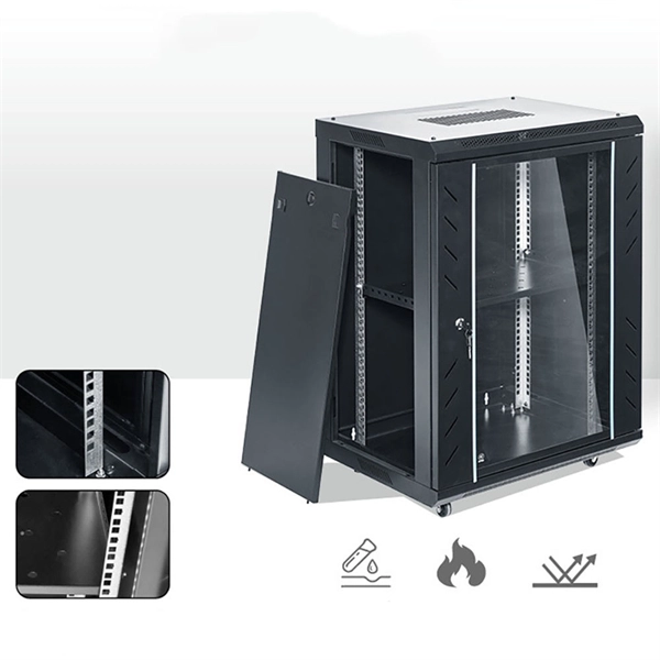
Cable Tray Development Model
Download this free 3D print file designed by AG3D. A fully modular snap together cable track system. System includes internal pathways for wire routing with snap fit lids for ease of service and installation. Why use cable tray? A properly designed and installed cable tray system provides outstanding reliability for a facility's control, communication, data, instrumentation and power systems cabling and wiring. There are T, Y, 90° and 45° junctions, as well as. Discover all CAD files of the "Cable trays" category from Supplier-Certified Catalogs ✅ SOLIDWORKS, Inventor, Creo, CATIA, Solid Edge, autoCAD, Revit and many more CAD software but also as STEP, STL, IGES, STL, DWG, DXF and more neutral CAD formats. Select a containment product and define alignment, elevation, offset, and bend and branch types and you are ready to start modelling.
[PDF Version]