-
Cost of Vertical Installation of Optical Cable
The cost to install fiber optic cable ranges from $1. 50 to $42 per foot, with installation costs accounting for 60-80% of total project expenses. According to the Fiber Broadband Association's 2025 report, median costs are $8 per foot for aerial builds and $18 per foot for. Fiber-optic cable pricing depends on whether you're purchasing materials alone or including complete installation. The main cost drivers include material type, run length, trenching or aerial work, and any required permits or inspections. This breakdown gives you real numbers to build better estimates. We'll show actual costs for.
-
Test Report on a New Vertical Cavity Surface Emitting Laser
Recent results on highly reliable 940nm multi-junction high power vertical-cavity surface-emitting lasers (VCSELs) are presented with target applications in depth sensing and Light Detection Ranging (LiDAR) markets. Vertical-cavity surface-emitting lasers (VCSELs) having a small aperture and operating in a single transverse mode (SM) are known to reach high relaxation oscillation frequencies of 30-90GHz and, thus, can offer intrinsic modulation bandwidth beyond 100GHz, once photon damping and electric. In this work, we present a high-performance vertical cavity surface emitting laser (VCSEL) based on a single-crystal CsPbBr 3 microplatelet, fabricated through a simple solution process and sandwiched between two distributed Bragg reflector (DBRs). Our innovation, the antireflective.
-
Chilean Quality Assured Vertical Cavity Surface Emitting Laser QSFP
The surface emission from a bulk semiconductor at ultra-low temperature and magnetic carrier confinement was reported by Ivars Melngailis in 1965. The first proposal of short VCSEL was done by Kenichi Iga of Tokyo Institute of Technology in 1977. A simple drawing of his idea is shown in his research note. Contrary to the conventional Fabry-Perot edge-emitting semiconductor lasers, his invention comprises a short laser cavity less than 1/10 of the edge-emitting lasers vertical to a wafer s.
-
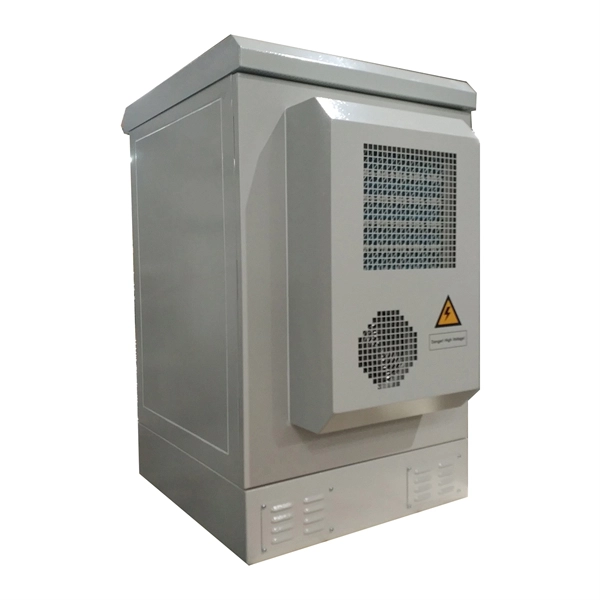
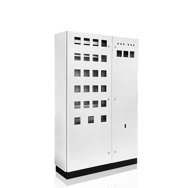
Vertical circuit of distribution box
Larger commercial, public, and industrial installations generally use three-phase supplies, with distribution boards which have twin vertical rows of breakers. Larger installations will often use subsidiary distribution boards.OverviewA distribution board (also known as panelboard, circuit breaker panel, breaker panel, electric panel, fuse box or DB box) is a component of an that divides an electrical power feed into subsidiary. North American distribution boards are generally housed in enclosures, with the positioned in two columns operable from the front. Some panelboards are provided with a door covering th. This picture shows the interior of a typical distribution panel in the United Kingdom. The three incoming phase wires connect to the busbars via a main switch in the centre of the panel. On each side of the panel are two.
-

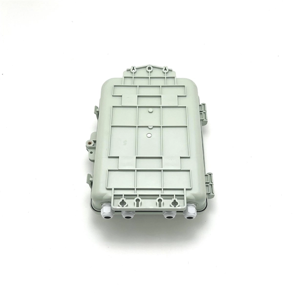
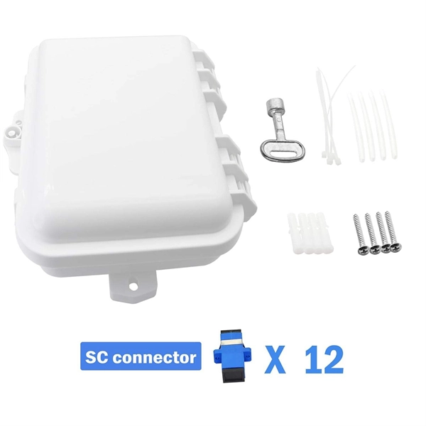
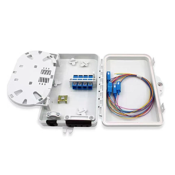
Detailed introduction inside the fiber distribution box
It organizes connections, splices fibers, and distributes signals in networks like FTTH (Fiber-to-the-Home) or FTTB (Fiber-to-the-Building). The box ensures fibers stay safe from damage and environmental factors. FDBs come in wall-mounted or pole-mounted designs. Fiber Distribution Boxes (FDBs) are critical components in modern telecommunications infrastructure, particularly in fiber optic networks. They function as junction points that manage, protect, terminate, and distribute fiber optic cables, ensuring efficient data transmission between different. A fiber optic distribution box, also known as a fiber optic terminal box or fiber optic termination box, is a device used to connect and manage fiber optic cables in a network.
-
Spacing of cable tray supports inside electrical wells
The NEC requires that cable trays must be supported by members at an interval specified by the cable tray manufacturer, but not more than 5 feet for horizontal runs to support the weight of the cables and other loads. The NEC has a requirement for ladder-type cable trays. Cable trays are used for supporting. Article Summary: A compliant cable tray installation requires a thorough understanding of NEC Article 392, proper structural support, and precise installation techniques. These systems, made from metal or plastic, are open structures designed to support electrical conductors, ensuring proper organization and safety. Cable tray is the preferred wiring method for industrial facilities, data centers, and large commercial buildings where routing dozens or. maintain spacing or to keep cables in place when the tray is ect the minimum bend ra-dius for cables as they exit the bottom of the cable tray. A rung spacing of 6 to 9 inches (150 to 230 mm) is preferable when the cable tray cont d for instrumentation and control applications that require.
[PDF Version]
-
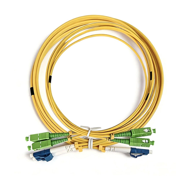
There are several fiber optic cable connectors inside the optical cable
The options on these cables dictate the fiber type, connector type, polarity, and polish type. The fiber types are SMF (Single-mode fiber) and MMF (multimode fiber). The fiber connector types, sometimes referred to as terminations, link fiber optic cables together through terminals, switches, adapters, and patch panels, by bridging the gap between their. While there are many different styles of connectors for single-fiber and multi-fiber cable assemblies, all basically share a similar construction. This article presents a brief overview of these key components. Fiber optic cables carry information between two places using entirely optical (light-based) technology. 5 µm wide, the alignment tolerance for any type of fiber. An optical fiber connector is a device used to link optical fibers, facilitating the efficient transmission of light signals.
[PDF Version]
-
Spacing of vertical shaft cable tray fixing supports
Cable Management Tray Size: Choose a tray size that will hold the desired amount and length of cable. Support Spacing: Remember the NEC requires no more than 4 feet of support spacing. The National Electrical Code is a set of principles designed to promote public safety and welfare, as well as safeguard public health by regulating the design and operation of electrical facilities and. Article Summary: A compliant cable tray installation requires a thorough understanding of NEC Article 392, proper structural support, and precise installation techniques. This guide covers the critical steps, from selecting the right electrical cable tray and performing accurate cable fill. maintain spacing or to keep cables in place when the tray is ect the minimum bend ra-dius for cables as they exit the bottom of the cable tray. Proper installation can significantly reduce electromagnetic interference, prevent fire hazards, and improve overall efficiency. Clause 522-08-04 Where conductors or cables are not supported.
[PDF Version]
-
Manufacturing of Trapezoidal Cable Tray Elbows
Professional Cable Tray Elbow Making | Metal Fabrication Tutorial Learn how to make cable tray elbows professionally with step-by-step guidance. Whether you are a DIY enthusiast. Search by Cooperative Patent Classifications (CPCs): These are commonly used to represent ideas in place of keywords, and can also be entered in a search term box. If you're searching for seat belts, you could also search for B60R22/00 to retrieve documents that mention safety belts or body. Cable trays and fittings from Selco Manufacturing offer distinct advantages for various applications. The following are some key benefits and considerations to guide your selection process. There are several essential benefits of using cable trays from Selco Manufacturing, including: Better. This manual is designed to guide workers through the detailed production process of ladder cable trays, including the manufacture of horizontal elbows, tees, crosses, reducing bends, and vertical bends, with emphasis on precision, safety, and quality control.
[PDF Version]
-
Cable vertical quota along cable tray
Cable Types: Only use conductors rated for open-air environments, such as Tray Rated (Type TC) or Metal-Clad (Type MC) cables. Cable tray types, fill rules for single-conductor and multiconductor cables, ampacity derating, separation requirements, and when to use tray vs conduit. Our free calculator helps you determine the correct tray size based on NEC and IEC standards. Follow these simple steps: Define Tray Dimensions: Enter the width and depth of your planned cable tray (in mm or inches). This is a description of how to select, install, and support these metal or plastic frames, on which electrical wires are installed. NEC 392 Fill Rules by Tray Type 3. Step-by-Step Calculation Example 4. Common Mistakes to Avoid NEC 392. This guide covers the critical steps, from selecting the right electrical cable tray and performing accurate cable fill calculations to managing a safe cable pull through and ensuring all bonding and grounding requirements are met. For licensed electricians, mastering these principles is essential.
[PDF Version]