-
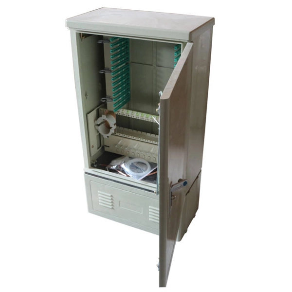
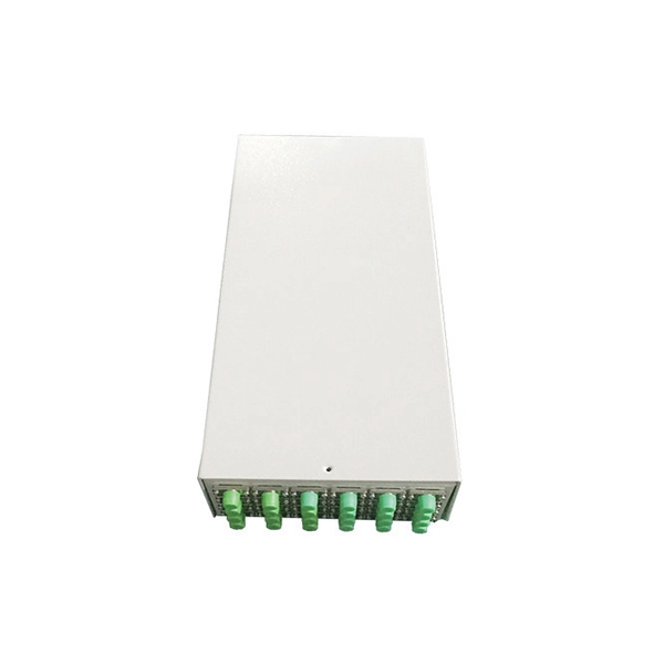
What is a fiber optic cable management rack also called
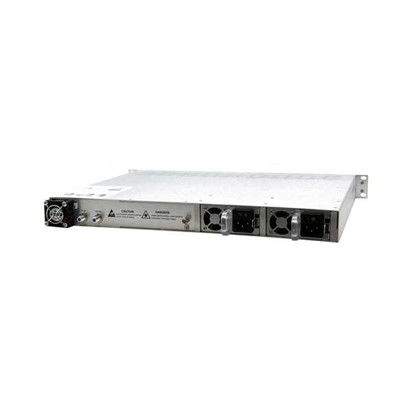
Also known as fiber optic enclosures or fiber entrance cabinets, these enclosures act as hubs where cables can be spliced, organized and routed through areas inside or outside a building. This article provides a clear technical view of cable management racks, their structures, and how to select the right solution for modern networks. It houses and protects fibre terminations, allowing you to manage high volumes of optical connections in a secure, scalable format. The Rack Mounted Optical Cable Terminal Box is a metal enclosure used for fiber cable. Fiber enclosures come in two primary types: wall mount and rack mount. On the other hand, rack-mount fiber enclosures are employed between or within. What Is a Fiber Patch Panel? A fiber patch panel is a mounted enclosure—either rack-mounted or wall-mounted—used to terminate, manage, and interconnect multiple fiber optic cables. Given its immense significance, it is essential for.
[PDF Version]
-
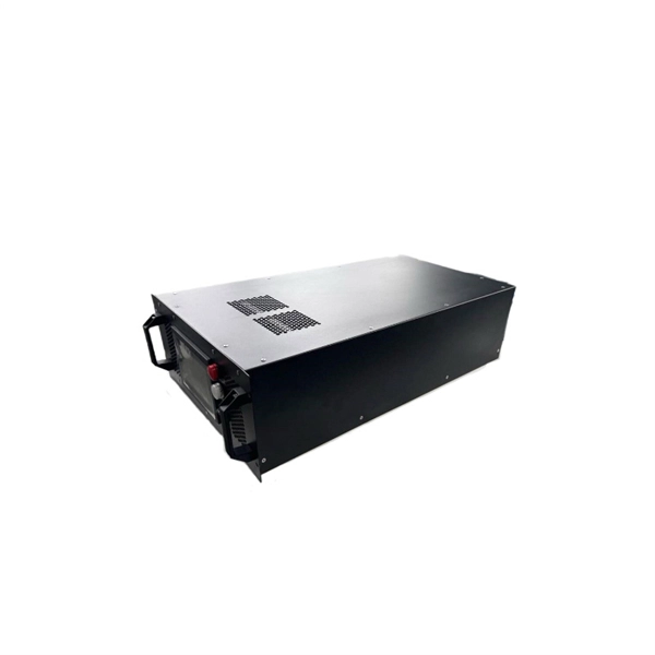
What is a server with a cable management rack called
A rack server is a computer designed to fit into a standardized rack framework, typically 19 inches wide. They are modular, allowing multiple servers to share power, cooling, and cabling infrastructure. Rack. Server racks and cable management systems are the backbone of any organized IT environment, from small office server closets to enterprise data centers. Get it wrong. A data center rack is a standardized frame structure designed to securely house IT equipment such as servers, switches, storage systems, and power distribution units. Let's explore the essentials of server rack cabinets and why they are indispensable in IT setups in business.
-
The role of cable management in cable tray bundling in computer room
Managing cables in cable trays is not only essential for improving the orderliness of cable installations but also for optimizing maintenance and troubleshooting processes. A well-documented infrastructure is easier to add onto, upgrade, change and maintain. Defining Network Cable Management Network cable management encompasses the tools, techniques, and infrastructure used to organize, protect. Efficient and organized network cable management in telecom rooms is critical, as disordered cables not only appear chaotic but can also compromise equipment performance and overall network reliability. For Stand-By UPS systems, the families are Internet Office, BC Pro® and BC Personal®.
-
Should the cable management rack be installed in the front or the back
Leave space for cable management —especially in the back. Ensure front-to-back airflow by leaving gaps or using filler panels. This method helps maintain neatness and accessibility within the rack while ensuring efficient airflow and ease of maintenance. Both overhead and under floor pathways should be designed to support the weight of cables in the initial installation and it should also facilitate the addition of future cables. With proper design and structured tools, it helps organize cables, ensure stable signal transmission, simplify maintenance, and improve overall system. Here are some best practices for rack placement: Implementing hot and cold aisle containment is a fundamental strategy for improving airflow and cooling efficiency. The racks should be positioned in a way that optimizes.
-
Complete Guide to Cutting Inner Bends of Cable Trays
This guide explains how to make 90° bends, vertical bends, tees, and offsets in wire mesh cable trays safely and professionally. Horizontal 90° Bend (Flat Bend) 2. Cross Bend (4-Way. OTHER THAN 90 ̊ JUNCTIONS Use this guide to learn the most effective installation practices when installing Cablofil tray. Each example of bends and tee's clearly illustrate proper tray cutting combined with recommended usage of Cablofil accessories. Oglaend System manufacture and deliver Multidiscipline modular bolted support systems, cable trays, cable ladders and accessories for complete installation and containment of Instrument, Electrical, Telecom, HVAC and Piping. Hubbell Wiring Device-Kellems and Hubbell Premise Wiring are divisions of Hubbell Incorporated, a U. headquartered manufacturer with over 130 years of supplying solutions for the electrical and data markets.
[PDF Version]
-
Selection Guide for OSFP and QSFP Optical Modules Used in Supercomputing Centers
This article compares OSFP and QSFP-DD in terms of physical dimensions, power and thermal characteristics, and compatibility, providing practical guidance for data center and network infrastructure planning. In the rapidly evolving landscape of high-performance computing and AI infrastructure, NVIDIA optical transceivers have emerged as critical components for enabling next-generation 800G network deployments. This guide gives you the complete picture. Our study of OSFP transceiver technology will begin with basic concepts and continue until we reach advanced technical. Today's mainstream 400G optical modules use three primary form factors: QSFP-DD, OSFP, and QSFP112. This article provides a comprehensive comparison of the three. In 2025, the optical transceiver market has shifted decisively. On the path to the 400G era, different form factors act as distinct engines, delivering.
[PDF Version]
-
What are the components of an optical guide driver module
The optical module is usually composed of Transmitter Optical Subassembly (TOSA, containing a laser LD Chip), Receiver Optical Subassembly (ROSA, containing a photodetector PD Chip), a driving circuit, and an optical and electrical interface. Its schematic is shown in Figure 1. The internal structure of an optical module is complex but can be divided into several main parts. It is the core device for connecting communication equipment with optical fibers. Operating at the physical layer of the OSI model, optical modules are core devices in optical. As an important part of fiber-optic communication, an optical module is a photoelectric converter which converts electrical signals into optical signals and vice versa. Composition of Optical Modules The optical module, known as Optical Transceiver in. The optical module serves as a crucial component in optical fiber communication systems, operating at the physical layer, which is the lowest layer in the OSI model.
[PDF Version]