-
Complete Guide to Cutting Inner Bends of Cable Trays
This guide explains how to make 90° bends, vertical bends, tees, and offsets in wire mesh cable trays safely and professionally. Horizontal 90° Bend (Flat Bend) 2. Cross Bend (4-Way. OTHER THAN 90 ̊ JUNCTIONS Use this guide to learn the most effective installation practices when installing Cablofil tray. Each example of bends and tee's clearly illustrate proper tray cutting combined with recommended usage of Cablofil accessories. Oglaend System manufacture and deliver Multidiscipline modular bolted support systems, cable trays, cable ladders and accessories for complete installation and containment of Instrument, Electrical, Telecom, HVAC and Piping. Hubbell Wiring Device-Kellems and Hubbell Premise Wiring are divisions of Hubbell Incorporated, a U. headquartered manufacturer with over 130 years of supplying solutions for the electrical and data markets.
[PDF Version]
-
Stress on cable trays
Material selection: Cable trays are typically made from steel, aluminium, or fibreglass. Choose materials that meet or exceed industry standards (e. Is your cable tray system optimized for safety, dependability, space and cost savings? Cable tray (or cable ladder) systems are a popular alternative to electrical conduit systems, as they have an outstanding record for dependable service, design flexibility and cost savings in commercial and. This appendix provides the design criteria for seismic Category I cable trays and their supports. Seismic Category II cable trays and their supports are also designed utilizing the design criteria of this appendix. The selection of material and finish is a function of the environment in wh tant in a wide range. Cable trays are an essential part of modern electrical and communication infrastructure, providing critical support for power cables and wiring systems. The concept of “Cables in Free Air” for power distribution and control cables has been adopted primarily for economic reasons. Ensuring the structural stability of these systems is paramount to prevent accidents, downtime, and economic losses.
[PDF Version]
-
Metrology Standards for Cable Tray Supports
The International Electrotechnical Commission (IEC) provides detailed guidelines for cable tray systems under IEC 61537. This standard outlines the construction requirements, testing methods, and performance parameters for cable trays and related support systems. Covers construction and test requirements for. Cable tray systems provide a safe, organized, and flexible method for supporting insulated conductors and cables in commercial and industrial electrical installations. When properly selected and installed, cable trays simplify routing, improve accessibility, and support future expansion while. us-trations without notice.
-
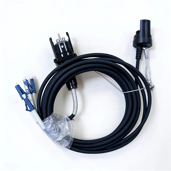
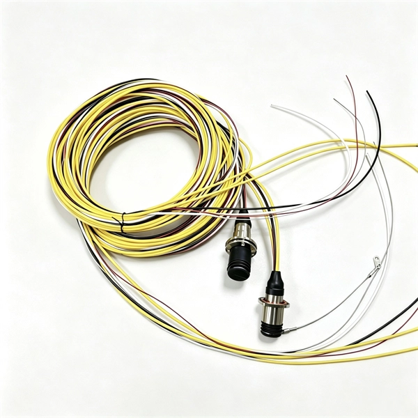
Fiber optic cable outer sheath representation
1 The outer cable jacket shall be marked with the manufacturer's name, date of manufacture, fiber count, fiber type, flame rating, listing symbol, and sequential length markings every two feet (e., “CORNING OPTICAL COMMUNICATIONS OPTICAL CABLE - MM/YY. XXXXX (feet. One important consideration when selecting indoor fiber optic cables is the outer sheath material and its fire prevention level. Each cable is single packed in a polybag with a test report that guarantees best performance in typical application scenarios like telecommunication, rack cabling, sensor technologies or indust Choosing the appropriate outer sheath material for fiber optic cables is crucial for ensuring the cable's durability, protection, and performance under specific environmental conditions. At the same time, it must have. 1. 1 The cable shall meet all requirements stated in this specification. Glass fiber and plastic fiber is fragile.
[PDF Version]
-
Optical cable channels are divided into
The light signal is divided into multiple channels with different frequencies and wavelengths, each transmitting a different data stream. In general, the fiber cable link system will be more secure if the fewer fiber cable segments. This region occupies a bandwidth of 95nm or 11THz! 8 cn cor where L is the fiber length, c is the speed of light, and ncor and nclad are the core and cladding refracitve indexes, respectively. Why not always use SMF? Optical phase information is lost in the detection process. What is a wavelength? What are optical wavelengths? What are nominal. In telecommunications, frequency-division multiplexing (FDM) is a technique by which the total bandwidth available in a communication medium is divided into a series of non-overlapping frequency bands, each of which is used to carry a separate signal. It essentially consists of a data transmitter, a transmission fiber (in some cases with built-in fiber amplifiers), and.
[PDF Version]
-
Single-mode port connected to multimode fiber optic cable
Single mode and multimode fiber cables are quite different when it comes to size, light source, signal, and so on. So, they definitely are not interchangeable, and compatibility issues can occur when you try to connect a single mode fiber optic connector to a multimode network. This is where fiber conversion comes in. Single-mode. To realize the short-range direct connection to the end B switch with the same port, the same 10GBASE-SR SFP+ module should be plugged into the end B switch port. What if end B is located in. It's possible because Multi-mode optical cables have a very wide fiber core – 62. Understanding the key differences between these two technologies is essential for IT professionals, business owners, and even homeowners looking to future-proof their network.
-
Translate the cable tray by 45 degrees
To create a 45-degree bend, cut the side rails to remove a segment calculated by the formula (Tan (22. Google's service, offered free of charge, instantly translates words, phrases, and web pages between English and over 100 other languages. So basically from my middle line what size to mark either side to cut my lip away to create different angles. Calculate horizontal, vertical, or compound cable tray offsets based on bend angle, offset distance, and available installation space. Measure this distance along the straight tray. ADVANCED S PRODUCTS I ASP 45° inuous system as well as stand-alone elements. 5∘ cuts on two separate pieces of cable tray. The second piece's cut must be in the opposite direction. Easy step to make 45 degree offset cable tray/Pipe and Air duct Cable tray 90 Degree Bend ! Cable tray ( Hindi) Cable tray 22. Distance of 145 mm ×.
[PDF Version]
-
Bangladesh finished optical cable
Find single-mode, multi-mode, and armored fiber cables for FTTH, data centers, and backbone networks. Shop with confidence at Smart View BD for the best price in Bangladesh with genuine products and official warranty. Is A Leading Manufacturing Industry Of Optical Fiber Cables (OFC) Of The Country With Fourth Generation German Technology Machineries. Order online to get delivery in BD. Our factory is located at Plot-10, Block-04, kaliakoir Hi-Tech park Industrial Estate which is at the heart of the Gazipur City Corporation.
-
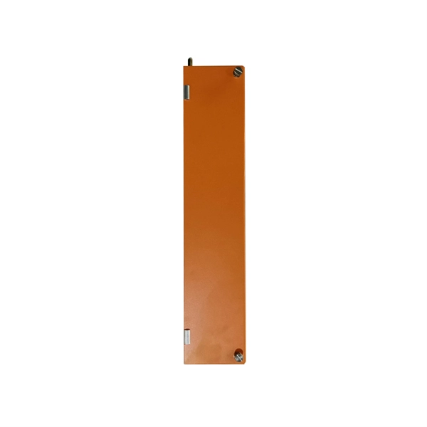
Manufacturing Process of Mesh Cable Tray End Plates
Watch how precision welding and automation technology transform raw materials into high-quality, durable cable tray mesh. 🔹 Key steps: ✔ Linear feeding – insert the straight line into the feeding trolley and feed it into the welding system controlled by the servo motor; ✔. Wire mesh cable trays are widely used in modern electrical wiring systems due to their open structure, excellent ventilation, and ease of installation. Compared to ladder or solid-bottom trays, they are more flexible and better suited for complex environments. more This video will show the complete process of manufacturing. Cable tray manufacturing relies on a coordinated production line of specialized machines: a roll forming line shapes the profile, a CNC press brake handles secondary bending, a punch press creates mounting holes and ventilation slots, and a shearing line cuts the finished tray to length. Together. Finally, surface treatment, such as powder coating or hot-dip galvanizing, provides corrosion protection and a finished look.
[PDF Version]
-
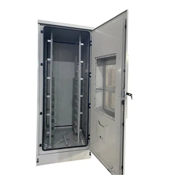
Cable Tray Internal Wiring Method
NEC Article 392 explains cable trays, their components, appropriate wiring methods for cable trays, and instances where they are and are not permitted for use. It also focuses on construction and installation practices for cable trays. Here is the summary of the main points found. Hubbell Wiring Device-Kellems and Hubbell Premise Wiring are divisions of Hubbell Incorporated, a U. headquartered manufacturer with over 130 years of supplying solutions for the electrical and data markets. The Cable Tray ng standards, performance standards, test standards and application in this document have been tested extens ompetent professional en completely installed, without damage either to conductors or. The B-Line series Cable Tray Manual was produced by our technical staff. Cable trays give cables a clear path.