-
What is the maximum value of a fiber optic pigtail
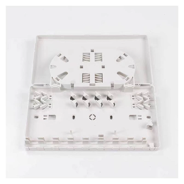
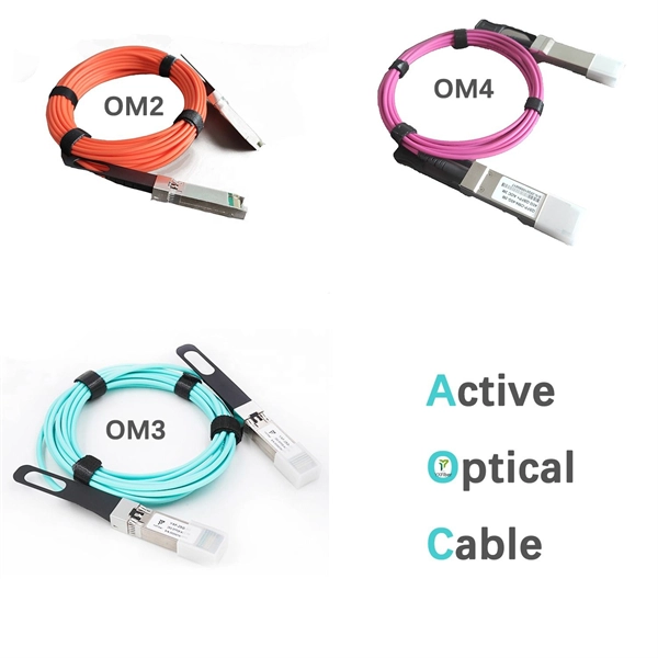
The pigtail sets are designed to operate over a wide range of wavelengths, ranging from 850nm to 1300nm for multi-mode and 1310nm to 1550nm for single-mode fiber with guaranteed low loss and reliability. Each pigtail is individually tested and supplied with a test certificate. Executive Summary: A fiber optic pigtail is one of the most commonly specified yet least understood components in structured cabling. Get the wrong connector type, the wrong polish, or skip proper fusion splicing technique—and you're looking at elevated signal loss, increased back reflection, and a. OPTICO offers a full line of simplex or Bundle Fiber Pigtails. It is at the end of the SC/LC/ST/FC/E2000 / MTP/MPO/MTRJ optical fiber connector, the other end for termination by fusion or mechanical splicing fiber optic cable. 5m to 2m—that has a factory-terminated connector on one end and bare fiber on the other end. The connector end is polished and tested under factory conditions, ensuring low insertion loss and high. PPC ofers sets of high-performance pigtails colored in compliance with TIA-598-C standard for all types of fiber optic networks.
[PDF Version]
-
Armenia Passive Optical Network Low Voltage Circuit
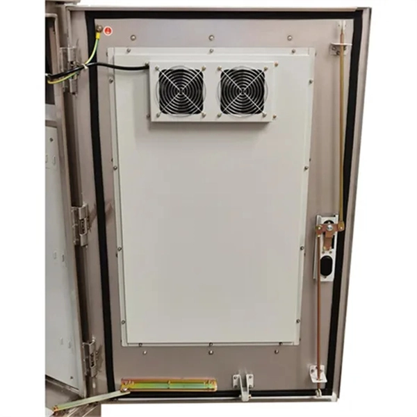
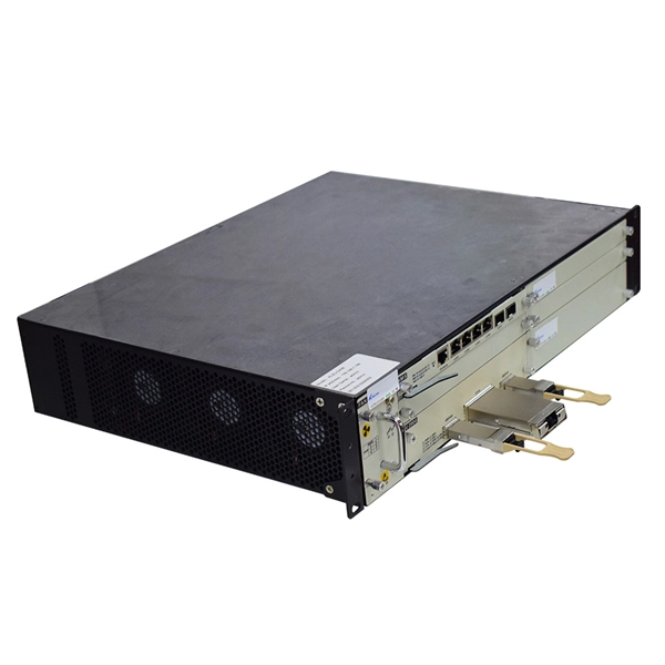
INCRIPT provides project development and management, turnkey solution implementation, installation, commissioning, and technical maintenance of low-voltage systems. The Relevance Inspector will open in the Coveo Administration Console. Our integrated circuits and reference designs help you create optical network terminal (ONT) units that enable high-speed data connections for today's passive optical networks. Use the resources below to design a system with our. INCRIPT emerges as a proficient systems integrator with over a decade of extensive experience in the Armenian market. Since its inception, the company has continuously evolved, refining its expertise in designing, building, and upgrading IT infrastructure and engineering systems. We offer turnkey. This paper presents the design and implementation of a passive optical network (PON) based on a gigabit-capable passive optical network (GPON) standard to deliver fiber-to-the-home (FTTH) services in a small-town setting. 5% of people in rural areas have access to the Internet, but only 73. The construction and deployment.
[PDF Version]
-
Circuit Breaker Relay Protection Equipment Model
Microprocessor-based solid-state digital protection relays now emulate the original devices, as well as providing types of protection and supervision impractical with electromechanical relays.OverviewIn, a protective relay is a device designed to trip a when a is detected. The first protective relays were electromagnetic devices, relying on coils operating on moving par. Electromechanical protective relays operate by either, or. Unlike switching type electromechanical with fixed and usually ill-defined operating voltage thresholds. Electromechanical relays can be classified into several different types as follows: "Armature"-type relays have a pivoted lever supported on a hinge or knife-edge pivot, which carries a moving contact. These relays may.
-
How to Select a Beam Splitter Circuit
This is vital in diverse fields from scientific research to consumer electronics. They operate with coherent or incoherent light, splitting by intensity, wavelength, or polarization. Plate beamsplitters are. Beamsplitters are used in laser systems, optical interferometry, fluorescence, and biomedical instrumentation. This division allows for the simultaneous analysis or utilization of the light's properties along two separate paths. See the Comprehensive Guide for worked examples, SVG diagrams, and full references.
-
Adjusting the distribution box circuit
Check the electrical load and ensure that the sensors do not exceed the 10 Amp maximum. They are installed in series between the Source and Load. They are a voltage source, they add or subtract. A distribution box, also known as a distribution board, electrical panel, or breaker box, is an enclosure that houses electrical components responsible for distributing electricity throughout a building.