-
Construction Scheme for Horizontal Cable Trays
The National Electrical Code (NEC) is the ultimate authority for any cable tray installation. Specifically, NEC Article 392 governs the use, installation, and construction specifications for these systems. Hubbell Wiring Device-Kellems and Hubbell Premise Wiring are divisions of Hubbell Incorporated, a U. headquartered manufacturer with over 130 years of supplying solutions for the electrical and data markets. Hubbell's strength is demonstrated by a long-standing reputation for supplying reliable. A printable 2-page reference card sent to your inbox. Need to renew your Electrician license? Pick your state and browse state-approved Electrician CE courses — complete your continuing education hours online, with instant reporting. Source Limitations: Obtain cable tray components through one source from a single manufacturer.
-
Horizontal deviation of each meter of horizontal cable tray
Horizontal deviation: ≤2mm per meter. Must be level, plumb, and securely mounted on supports. Calculate horizontal, vertical, or compound cable tray offsets based on bend angle, offset distance, and available installation space. Use dedicated splice plates and. The maximum horizontal distance shall be 76-meters (250 ft). For ease of cable installation and future expansion in hallway or major distribution routes, cable trays are the preferred method for distributing the horizontal wiring from the telecommunications room to the communication outlets. When. NEMA Standards Publication VE 2-2018 Cable Tray Installation Guidelines Endorsed by Cable Tray Institute www. com Published by: National Electrical Manufacturers Association 1300 North 17th Street, Suite 900 Rosslyn, Virginia 22209 www. This spacing should generally be no less than 0. The primary reason for this separation is to minimize electromagnetic interference (EMI), which could.
[PDF Version]
-
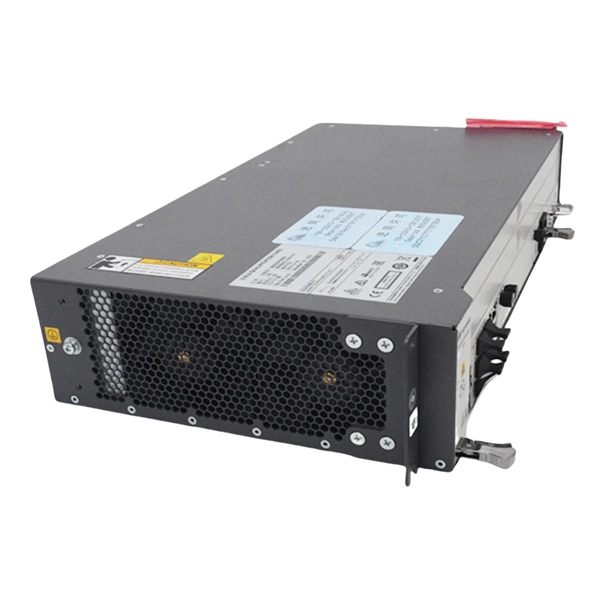
How to connect RRU optical modules in series
A fiber optic cable connects the RRU to the RBS main unit or an expanded macro RBS. The RRUs can be connected in a cascade configuration and a star configuration with optical cable links. User Guide About This Document About This Document Purpose This document describes the RRU hardware and provides instructions in hardware installation, cable connections, hardware installation check, and hardware maintenance. It also provides checklists as reference. In this document, eRRU3232 is used as an example. When wrapping the waterproofing tape, apply even force to extend the tape until the width of the tape is 1/2 of the original width. Start-up Below you will find brief information for RRU RFD01F Series.
-
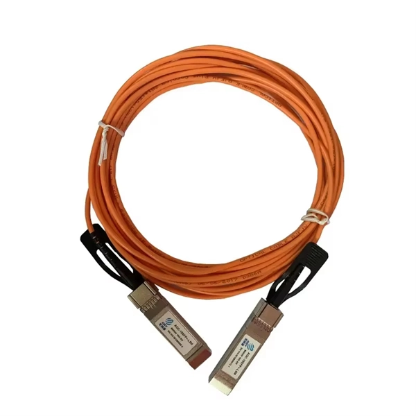
Can optical fibers be connected in series
It is worth noting while one optical core can connect to multiple terminal devices in a series. Consequently, long-distance transmission may not be feasible or experience significant signal. The number of optical cores in an optical fiber is the total number of equipment interfaces multiplied by 2, plus 10% to 20% of the spare quantity, and if the communication mode of the equipment has serial communication and equipment multiplexing, you can reduce the number of cores. Fusion Splicing: This method involves aligning the ends of the two fiber optic cables and then fusing them together using heat. This creates a permanent and low-loss connection. A verification email has been sent to {0}. Most systems operate by transmitting in one direction on one fiber and in the reverse direction on another fiber for full. An optical fiber connector is used to join optical fibers where a connect/disconnect capability is required.
[PDF Version]
-
How to install the cable tray beam bend
The fittings can fastened to the cable tray rail either with double clamps of type DOP A2 or with truss-head bolts of type FRS and combination nuts. The exceptions to this are vertical bends, adjustable bend elements and fittings with a side height of 35 mm. These fittings can only be screwed on. Beam bracket PK1 is attached to the lower flange of an I beam. These guidelines are not intended to cover all details or variations in cable ladder and cable tray. en completely installed, without damage either to conductors or structural system use maintain spacing or to keep cables in place when the tray is ect the minimum bend ra-dius for cables as they exit the bottom of the cable tray. A rung spacing of 6 to 9 inches (150 to 230 mm) is preferable when. Hubbell's NEXTFRAME® Ladder Tray is the effective and widely used cable runway that supports and delivers bundles of cable between cabinets, racks, and closets, along walls, and suspended from ceilings. Cable ladder systems and cable tray systems shall be manufactured in accordance with BS EN 61537, channel support.
[PDF Version]
-
Cable tray horizontal tee cutting method
Completely adaptable, B-Line Flextray is designed to accommodate jobsite changes. For the best results, use a WB30BC Angular Blade Offset Bolt Cutter . to produce a clean cut. Do not use center cut style cutters, as they will leave a rough, burred cut that can damage cables and/o oximately a 45° angle. Cut the bottom wires firs in the order as shown. Flip the tray. To properly bond Hubbell ® painted cable tray, remove the plastic masking device from the trays on each end (exposing the pre-galvanized wire), and splice sections together using Hubbell ® splice kits. For cable trays that are not UL Classified as being “Suitable as an Equipment Grounding. Horizontal Tees link three 10" straight channel sections or compatible transitional fittings, enabling the creation of a sleek and efficient horizontal branch within a fiber routing system. Item code: HT Reducing Tee: W1>W2. Only two splices are required to securely connect tray widths of wire basket tray. The. Use this guide to learn the most effective installation practices when installing Cablofil tray. Engineers and contractors in North America and around the world have found.
[PDF Version]
-
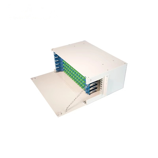
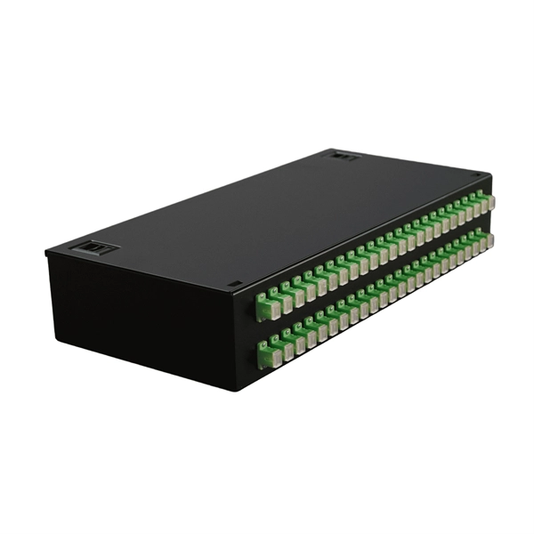
What is a horizontal optical cable junction box called
Fiber Cable Joint Box is a device used to provide space and protection for fiber optic cables spliced together. Optical cable splice boxes protect the splicing parts of optical fibers from various hazards, such as water seepage due to adverse. A Fiber Terminal Box (FTB) is a customer-side termination and distribution device used at the end of the optical network. ■ What Is a Fiber. Fiber optic splice closures are essential components in today's communication networks. These closures protect and organize splicingfiber connections, ensuring the integrity of opticalsignal transmission.
-
How much does a fiber optic patch cord production line cost
A complete fiber optic cable production line in 2025 requires an initial investment of $750,000 to $2,500,000. With strong market demand, most businesses achieve a full return on investment (ROI). This article dives deep into the financial and technical requirements for establishing a fiber cable production line. Understanding these elements is critical to developing a competitive strategy and estimating potential returns on investment. To get more information please contact us our technical help you from production line to raw materials and consuming material How to make Fiber Optic Patch Cord and. The report provides an analysis of the global fiber optic cable market performance, market breakup by segment and region, price trends, key market players and impact of COVID-19 on the market. Additionally, it offers insights into the market outlook, including growth opportunities and challenges.
[PDF Version]
-
How to connect the main cable to the branch line of the cable tray
Place screw head on inside of branch cable tray, put the jumper outside of branch cable tray, add flat washer and locknut, then tighten. Cable tray shall be grounded as defined in SAES-P-111 Section 7, 8, and 9 and NEMA VE-2 Section 4. Connecting cable trays correctly is essential for system safety, load stability, and long-term performance. Choosing the right one depends on project conditions, load. All cable trays and supports will be installed as shown on EPC approved design construction drawings and located to avoid interferences with other facilities. NEMA ratings are standards that define the types of environments an electrical enclosure can be used in. It ensures that all installation activities follow authorized plans, specifications, and standards.
-
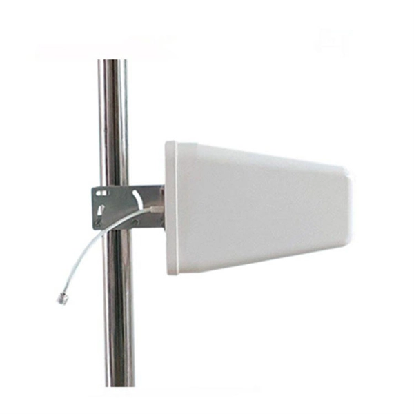
Is there a connection between power line carrier machines and optical cables
Thus there is a large distance between the equipment and the tuner, and the connection between the two is made using a coaxial cable Fiber Optical (FO) Cable. The coaxial cable provides shielding so that noise cannot get into the cable and cause interference. Optical attached cable (OPAC) is a type of fibre-optic cable that is installed by being attached to a host conductor along overhead power lines. These cables are installed on poles or towers at the. Communication networks are an integral part of interconnected transmission lines in a power grid, analogous to the spinal cord for control signal and information exchange among substations, data hubs, and load dispatch centers. Carrier current used for Power Line carrier Communication has a frequency range of 80 to 500 kHz. PLCC is mainly for telemetry and telecontrol in modern electrical. OPGW (Optical Ground Wire): This is an all-metal cable that holds a large number of optical fibers inside. What Are the Main Advantages of Aerial Fiber Cable? The main advantages of aerial.
[PDF Version]