-
CAD Engineering Cable Tray Filling
Download a comprehensive set of Cable Tray Installation CAD Blocks in DWG format, ideal for electrical engineers, MEP designers, and industrial layout planners. In the Electrical workspace, click Home tabBuild panel. The cable tray and conduit tools have specific. Paneldes Raceway is the 3D CAD design module of EDS used for the creation of Plant Raceway models. Paneldes software performs cable routing, cable filling and cable length calculations, as well as interference analysis and materials reporting. Paneldes Raceway software is for construction engineers. Discover all CAD files of the "Cable trays" category from Supplier-Certified Catalogs ✅ SOLIDWORKS, Inventor, Creo, CATIA, Solid Edge, autoCAD, Revit and many more CAD software but also as STEP, STL, IGES, STL, DWG, DXF and more neutral CAD formats.
-
Power Engineering OPGW Optical Cable
An optical ground wire (also known as an OPGW or, in the IEEE standard, an optical fiber composite overhead ground wire) is a type of cable that is used in overhead power lines. Such cable combines the functions of grounding and telecommunications. An OPGW cable contains a tubular structure with one or more optical fibers in it, surrounded by layers of steel and aluminum wire. The. HistoryAn OPGW cable was patented by BICC in 1977 and installation of optical ground wires became widespread starting in the 1980s. In the peak year of 2000, around 60,000 km of OPGW was installed worldwide. Asia, especially. Several different styles of OPGW are made. In one type, between 8 and 48 glass optical fibers are placed in a plastic tube. The tube is inserted into a stainless steel, aluminum, or aluminum-coated steel tube, with some slack lengt. Optical fibers are used by utilities as an alternative to private point-to-point microwave systems, or communication circuits on metallic cables. OPGW as a communication medium has some adva.
[PDF Version]
-
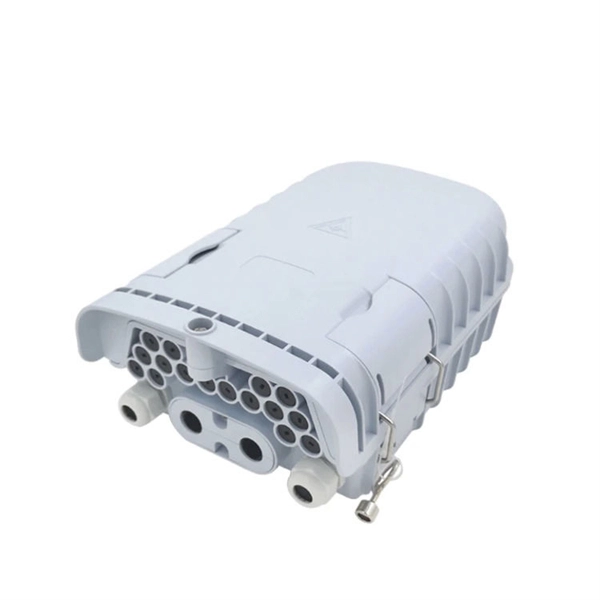
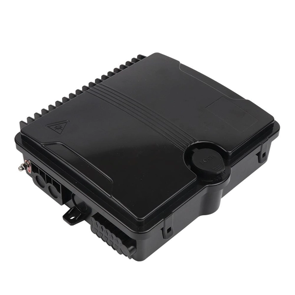
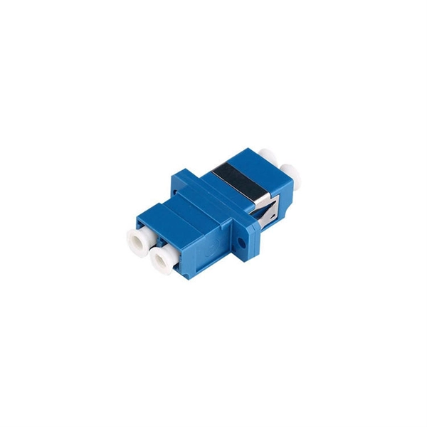
Installation of Optical Distribution Box in Telecommunications Engineering
This guide provides a comprehensive engineering perspective on ODFs—beyond the basic “what is an ODF” explanation—covering structural design, fiber management, MPO/MTP integration, and selection criteria for modern high-density deployments. Why ODFs are the Foundation. Fiber optic technology has revolutionized the telecommunications industry, enabling faster and more reliable data transmission. In this article, we will delve into the world of fiber optic distribution boxes -. technical specialist at Spring Optical, focusing on Data Center cabling Solution, FTTA Solution, FTTH Solution, and ODN Solution for global telecom, ISP, and data center network deployments. A fiber optic wall plate is a critical indoor FTTH termination component that connects fiber drop cables to. This instruction describes the installation of the Fiber Distribution Frame (FDF) manufactured by Corning Optical Communications. It can also be deployed in any cross-connect architecture and still provide clear, managed pathways for fiber. Determine the installation position: - Determine the installation position of the optical fiber distribution box based on the.
[PDF Version]
-
Protection Measures for Optical Cable Line Engineering
Optical cable lines lightning protection and strong current protection are achieved by avoiding, guiding or discharging them underground to prevent lightning and strong current from causing damage to the optical cable lines themselves, communication equipment and personnel. Since the lightning. The Fiber Optic Association, Inc. The conduit can be made of various materials such as PVC, HDPE, or steel. It is suitable for areas with flat terrain and small undulations. This type of fiber optic is laid in two ways: suspended under steel strand and self-supporting suspension. Local exchange carriers use fibres to carry the same service between central office switches at local levels, and sometimes as far as the neighbourhood or individual home.
-
Cost of Optical Cable Construction in Telecommunications Engineering
Home and business fiber optics projects typically range from a few hundred to several thousand dollars, depending on run length, fiber type, and labor needs. The main cost drivers are materials, installation time, and environmental factors that affect trenching, conduit, and terminations. Fiber optic network construction is linking together all forms of digital infrastructure to ensure that optical telecommunications traffic can seamlessly reach end users at the lowest possible cost. Fiber optic construction is bringing high-speed internet connectivity to homes and businesses in. BroadbandUSA collected information about network construction expenses to increase awareness of the costs associated with deploying a broadband network. This data is based on cost information.
-
Construction Scheme for Horizontal Cable Trays
The National Electrical Code (NEC) is the ultimate authority for any cable tray installation. Specifically, NEC Article 392 governs the use, installation, and construction specifications for these systems. Hubbell Wiring Device-Kellems and Hubbell Premise Wiring are divisions of Hubbell Incorporated, a U. headquartered manufacturer with over 130 years of supplying solutions for the electrical and data markets. Hubbell's strength is demonstrated by a long-standing reputation for supplying reliable. A printable 2-page reference card sent to your inbox. Need to renew your Electrician license? Pick your state and browse state-approved Electrician CE courses — complete your continuing education hours online, with instant reporting. Source Limitations: Obtain cable tray components through one source from a single manufacturer.
-
Horizontal deviation of each meter of horizontal cable tray
Horizontal deviation: ≤2mm per meter. Must be level, plumb, and securely mounted on supports. Calculate horizontal, vertical, or compound cable tray offsets based on bend angle, offset distance, and available installation space. Use dedicated splice plates and. The maximum horizontal distance shall be 76-meters (250 ft). For ease of cable installation and future expansion in hallway or major distribution routes, cable trays are the preferred method for distributing the horizontal wiring from the telecommunications room to the communication outlets. When. NEMA Standards Publication VE 2-2018 Cable Tray Installation Guidelines Endorsed by Cable Tray Institute www. com Published by: National Electrical Manufacturers Association 1300 North 17th Street, Suite 900 Rosslyn, Virginia 22209 www. This spacing should generally be no less than 0. The primary reason for this separation is to minimize electromagnetic interference (EMI), which could.
[PDF Version]
-
Bending angle of vertical bend in cable tray
A box type cable tray vertical outside bend is a fitting used to change the direction of a cable tray system vertically, typically at a 90-degree angle, directing cables outward. How to calculate cable tray bends? Calculate the minimum required bend radius by multiplying the cable's outside diameter by its bending factor (e. Then, select a standard tray fitting (300mm, 450mm, etc. ) that matches or exceeds this value. Use this tool to estimate sloped section length, horizontal run requirement, cut marks, and installation feasibility. Measure this distance along the straight tray. 90° bend, Vertical Inner Bend, for all cable tray types of 50 mm side height. How to bend 90 degree of cable tray 3 line with the same distance :// • HOW TO BEND 90 DEGREE OF CABLE TRAY 3 LINE.