-
What are the pros and cons of ladder-type and trough-type cable trays
(3) Ladders, trays, and trough boxes each have their own advantages and disadvantages; ladders have good ventilation performance, but are not dustproof and anti-interference. A cable tray is built for cable organization, protection, and flexibility. Choosing the right one depends on cable type, load requirements, environment, and long-term maintenance needs. Both systems hold wires, but they do not operate in the same way. When the incorrect one is selected, the wires may become overheated, or the metal support may even fracture under the. A cable ladder, also known as a ladder cable tray, is a support system that consists of two longitudinal side rails connected by individual rungs. Alternative names include: cable runway and. This blog clearly explains what cable trays and cable ladders are, outlines their key differences, and provides practical guidance to help you select the right solution for your installation. These trays ensure maximum airflow around the cables, promoting effective ventilation and heat dissipation to keep cable temperatures within safe limits.
[PDF Version]
-
Does optical fiber play a significant role in overhead power lines
The integration of fiber optics into overhead power lines has revolutionized how power grids operate, enabling greater efficiency, enhanced reliability, and improved safety. The evolution of power transmission systems has long been driven by the need for increased capacity and. For monitoring and managing networks, they use a variety of means of communications, including running fiber optic cables along the transmission and distribution towers, radio links and contracting landline and cellular communications services from telecom carriers. Utilities build fiber optic. Optical attached cable (OPAC) is a type of fibre-optic cable that is installed by being attached to a host conductor along overhead power lines. Utilities saw that, too, but to them, sending signals over glass solved a major problem: electrical interference from high-voltage transmission lines. Understanding their distinctions is essential before committing to either solution. What Are ADSS and OPGW Cables? All Dielectric.
[PDF Version]
-

How to route fiber optic cables for high-voltage power lines
This technique takes a small, lightweight fiber optic cable and wraps it around or lashes it to the power line. The cable is called optical power attached cable (OPAC), and it is lashed to the power cable with a specialized tool that is pulled from the ground, such as a. Installing ADSS (All-Dielectric Self-Supporting) cables near live power lines demands precision, compliance with safety standards, and an understanding of high-voltage risks. This guide from GL FIBER breaks down the process into actionable steps, aligned with IEEE 524 and IEC 61935-1 protocols, to. Most aerial fiber optic cables are installed by lashing to a steel messenger wire strung between poles, but there is a category of cables with special high-strength jacket designs called all-dielectric self-supporting (ADSS) cables. ADSS cables are designed to withstand very high-tension loads. bles in a high voltage environment, with typical line voltages of 115 kV or more, requires the evaluation of certain critical parameters. Curr ntly, there are a limited number of industry documents that address the requirements for optical fiber cables near high voltage circuits.
[PDF Version]
-
Testing Standards for Power Fiber Optic Cable Trunk Lines
FOA procedures, such as OFSTP-7 (single-mode) and OFSTP-14 (multimode), align with TIA and IEC standards. FOA standards help you with installation, testing, and troubleshooting in real-world conditions. These parameters ensure your network meets performance and compliance requirements. You need to measure how much signal is. d suppliers of electrical construction services. Existence. ANSI/TIA‑568. 3‑E “Optical Fiber Cabling and Components Standard” was developed by the TIA TR‑42. Scope: This Standard specifies performance, transmission, and test and measurement requirements for premises optical fiber cable. A practitioner-level walkthrough of the IEC 60794 framework: standard structure, mechanical and environmental test methods, type vs routine testing, common failure modes, and procurement specification guidance. Fiber optic testing of a newly installed system not only verifies that the system meets its design requirements, but also creates a performance baseline for all future testing and troubleshooting of t at system. The Contractor must utilize the correct equipment and testing techniques to gain acceptance, or the work cannot be approved.
[PDF Version]
-
Incident Power in Fiber Optic Communication
The incident optical power is used to suppress nonlinear effects and ensure transmission quality. In the following figure, optical power at point C is the incident optical power. Why Do We Need Incident Optical Power? The transmission performance of a WDM system is affected by the. This AE Note explains the differences between Optical Return Loss (ORL) and Back Reflectance in fiber optic systems. Even minor deviations—whether too high, too low, or unstable—can impact signal integrity, trigger service alarms, or interrupt traffic on DWDM, OTN, or long-haul optical line systems.
-
How are 36 cores of power optical fiber cable divided
Multi-core optical fiber is a breakthrough in optical networking that packs multiple cores into one fiber, enabling tremendous capacity gains via spatial division multiplexing. By carrying parallel channels in a single strand, MCF allows operators to multiply bandwidth without. These optical signals are transmitted (Tx) and received (Rx) at deliberate power levels expressed and measured in milliwatts (mW), an absolute optical power level. Absolute levels may also be represented as a relative optical power level, known decibel milliwatt or dBm. Its primary function is to split the optical signal of one input optical fiber into multiple optical signals and transmit them to. MTP/MPO cables are a class of high-density multi-core fiber optic connectivity solutions widely used in data centers and telecom networks, which are designed to achieve fast connection of multi-core fiber optics through a single interface. In contrast to conventional single-core fibers (one core on the fiber axis), MCF can have two or more.
[PDF Version]
-
Light collection power of the second-stage beam splitter
It is currently used in modern three-CCD cameras. An optically similar system is used in reverse as a beam-combiner in three- LCD projectors, in which light from three separate monochrome LCD displays is combined into a single full-color image for projection.OverviewA beam splitter or beamsplitter is an that splits a beam of into a transmitted and a reflected beam. It is a crucial part of many optical experimental and measurement systems, such as In its most common form, a cube, a beam splitter is made from two triangular glass which are glued together at their base using polyester,, or urethane-based adhesives. (Before these synthetic,. Beam splitters are sometimes used to recombine beams of light, as in a. In this case there are two incoming beams, and potentially two outgoing beams. But the amplitudes.
-
How are optical power meters classified
An optical power meter (OPM) is a device used to measure the power in an signal. The term usually refers to a device for testing average power in systems. Other general purpose light power measuring devices are usually called,, power meters (can be sensors or ), or lux meters. A typical optical power meter consists of a , measuring and display. The sens.
-
Can PoE power be turned off on a PoE switch
For TP-Link PoE switches, except for Unmanaged Switches, we can disable/enable PoE power on individual ports under PoE > PoE config, and PoE Status of PoE port is enabled by default settings. 08-27-2024 07:21 AM Just so we are confusing folks - We don't turn off switch port just to turn off PoE. To disable PoE only for an interface, go. Please note that the TL-SG108 doesn't support PoE at all. If a device does not need PoE the switch/UDM will not supply any power on that port. In the Network Operations app, select one of.
-
Power Grid Optical Cable Operation Level
Key OPGW testing methods include visual inspection, OTDR testing, optical power meter testing, continuity tests, and various mechanical and environmental tests. Each method targets a specific aspect of cable performance and safety. OPGW stands for Optical Ground Wire. These cables are used on high voltage power lines. I have managed many projects where I personally oversaw the testing process. I know that if testing. This specification defines the design, material, performance and test requirements for fibre optic cable to support the fibre optic telecommunication needs. How to calculate the required fault. ion infrastructure. Optical Ground Wire (OPGW)/Underground Fiber Optic Cable (UGFO) plays a crucial role in ensuring seamless data exchange, real-time monitoring, and reliable operati n of power systems. However, with increasing demands and multiple stakeholders involved in fiber usage, it became.
[PDF Version]
-
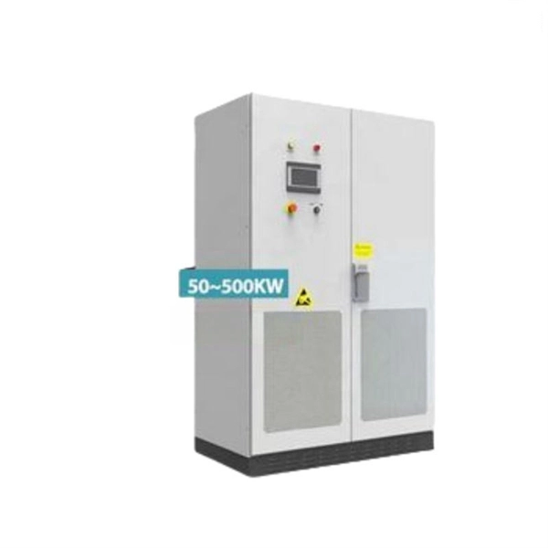
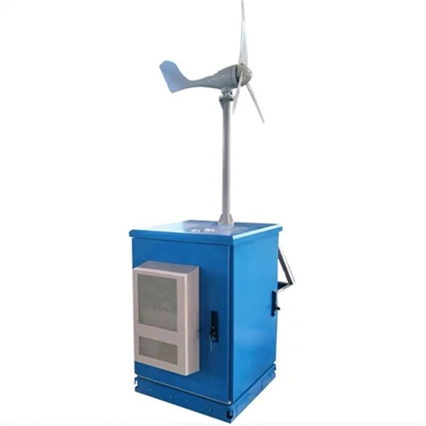
48V power supply for communication sites used in subways
This article presents a scalable and stackable –48 V DC PoL solution that will address the high density power usage situations created by these high density networks from the tremendous growth in network traffic. converting unstable AC input into stable, regulated 48V DC power for telecom equipment. Integrated DC system capability with controller and distribution module options, allow customers to have a complete DC Power System in 1U height. As DC power. The LXPower48200S is specially designed to meet the demand for compact, flexible, high performance, high reliability power supply. The system consists of 1-4 units LXPower3000 high/standard efficiency rectifier modules of their mixture, a LX2000 monitor module, AC/DC distributors. Because DC. The choice of -48V DC for powering telecommunications equipment is a standard practice rooted in a blend of historical precedent and a suite of technical benefits that ensure the robust, efficient, and safe operation of telecommunications networks. This standard is not arbitrary but is the result.
[PDF Version]