-
Intelligent Control of High Voltage Distribution Cabinets
Abstract: The intelligent control device can be used for 3~35kV indoor high-voltage switch cabinets, suitable for various switch cabinets such as central cabinets, handcart cabinets, fixed cabinets, ring network cabinets, etc. It integrates data acquisition, remote monitoring, fault protection, and communication management into a single unit. Featuring a modular design and customizable configurations, it. This is where precision power distribution and intelligent power monitoring step in—not as upgrades, but as a fundamental shift toward predictive, data-driven power management. This article follows a case-based narrative: from real operational pain points, to system conflict, to technical solution. Every payment you make on Made-in-China. com is protected by the platform. Claim a refund if your order doesn't ship, is missing, or arrives with product issues.
[PDF Version]
-
Maximum allowable voltage drop value of 10kV busbar
The formula used is IMAX = (I * 100) / (100 + VD), where I is the busbar current rating and VD is the allowable voltage drop. Typical values for LV installations are given below in Figure G27. 1) These voltage-drop limits refer to normal. Instant voltage drop limits calculator: NEC and IEC compliant, auto-applies 3%/5% rules for lighting, feeders. Enter nominal voltage and optional measured drop; get pass/fail, max allowable volts, length helper instantly. Design by percent limits: compute max length, minimum size or actual drop. Voltage drop is the reduction in voltage along a bus bar due to its resistance. This standard defines the design verification, test requirements, and thermal performance of the assemblies.
-
Function of Busbars in High Voltage Switchgear
A busbar is a metal bar, usually made of copper or aluminum, that carries electricity inside switchgear. It connects the incoming power to circuit breakers and outgoing circuits, helping power flow smoothly and evenly. Good busbar design helps prevent overheating and electrical. Busbar design in switchgear ensures safe, reliable power distribution by balancing current capacity, thermal performance, mechanical strength, insulation, and standards compliance. Electrical busbars are solid conductors used to carry and distribute high current in switchgear, panels, substations, and power systems. This guide explains how busbars work, common types, key design factors, and how to choose the right busbar for your application. Instead of running numerous.
-
Switch cabinet busbar installation
In North America, follow UL 891 construction and NEC Article 408 installation practices: use listed/approved hardware, lugs, or tap-off provisions intended for the bus. The matrix below helps engineers finalize material, arrangement, plating/insulation, and verification. The GRL busbar system makes distribution cabinet installation fast, flexible, and neat. At this stage, the supports have been installed in accordance with the installation plan. Ever wondered how busbars, the unsung heroes of electrical distribution, are processed and installed? This article delves into the intricate steps of busbar selection, preparation, and installation, ensuring efficient and safe power distribution. The application of these rules means strict compliance, not only with applicable regulations and standards, but also with manufacturers'. Bus bars play a crucial role in electrical distribution systems by providing a reliable and efficient way to conduct electricity within electrical panels.
[PDF Version]
-
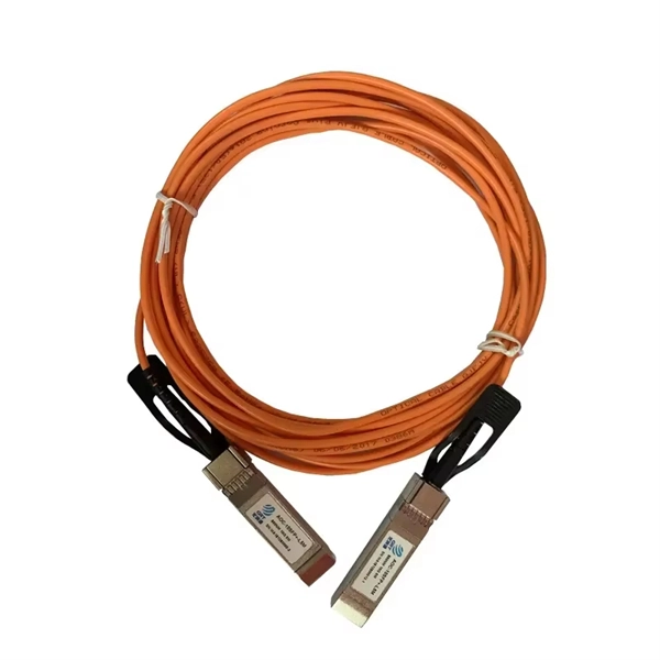
What is a two-optical switch
The basic form of an optical switch is 2×2, which means there are two optical fibers at both the input and output ends. This technology allows for high bit rate transmission to be switched between various optical lines. However, more advanced devices can route one. Optical Switches, or optical switches, are devices that have one or more selectable transmission windows and can perform mutual conversion or logical operations on optical signals in optical transmission lines or integrated optical paths.