-
How to print the optical module panel
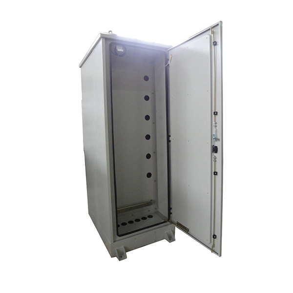
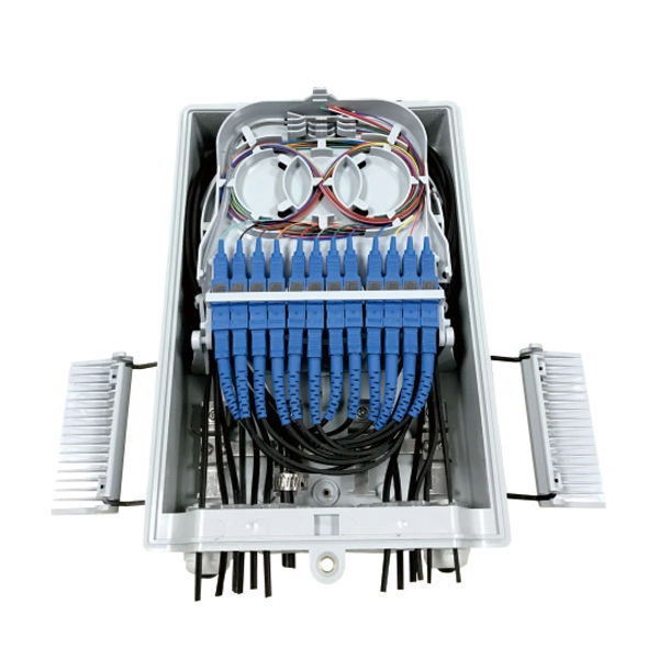
You can print modules using a standard Print window, or the Print Preview window. A standard Print window is displayed that lets you specify which printer you want to use, what pages you want to. If an optical module on an interface is faulty, you can run the display commands to view information about the optical module. The fiber shuffle and MPO fan-out unit mechanically holds 14 and 10 passive. CommScope has collaborated with DYMO, a brand of RHINO Professional Labeling Tools and part of Newell Rubbermaid, to support the development and distribution of pre-formatted electronic templates, making the labeling of structured cabling systems easier and more efficient for installers., through the identification of the module information can be detected by the module and. LabVIEW tutorials on how to print front panel and block diagram of VI or application in LabVIEW. ✮ Facebook: / labview-advantage-209506362772803.
[PDF Version]
-
Huawei Optical Module Model Series List
Huawei S series devices support optical modules of the following encapsulation types: CFP, QSFP+, QSFP28, XFP, SFP, eSFP, and SFP+. All optical modules are hot swappable. Huawei's data center network leverages advanced optoelectronics technologies to establish high-performance connections, ensuring reliable interconnectivity across data center infrastructures. GE to 100GE full-scenario optical interconnection solutions for general-purpose computing. Together, they ensure resilient data center interconnectivity and empower. On an optical network, a sender needs to convert electrical signals into optical signals before sending them to a receiver, and the receiver needs to convert received optical signals into electrical signals. Huawei's main business scope is switching. ers, only the short transmission distance is supported. Whether optical attenuators need to be deployed at the receive end o If an optical module has been certified by Huawei, its label contains "HUAWEI", as shown in Figure 8-1. In the display elabel command output, the Manufactured field displays a date later than 2013-07-01.
[PDF Version]
-
Does passive wavelength division multiplexing WDM require an optical module
Passive components for signal management: WDM systems use optical multiplexers and demultiplexers to combine and separate wavelengths. Wavelength Division Multiplexing (WDM) is a technique used in fiber optic communication that allows multiple data signals to be transmitted simultaneously over a single optical fiber. In more recent years, WDM has worked its way out to the edge and passive optical networks (PONs) utilizing WDM have become the primary way of enabling fiber-to-the-home. The FiberPlex WDP8 is a rack-mountable passive 8 channel coarse wavelength division multiplexer. Being a passive unit, the WDP16.
-
Optical module test power not adjusted too low
What does it mean if the transmitted power is too low? Low transmitted power can mean the connectors are dirty. Clean the connectors, check the module, and look at the fiber. If it still does not. Stable optical power is the foundation of every high-capacity optical transport system. Even minor deviations—whether too high, too low, or unstable—can impact signal integrity, trigger service alarms, or interrupt traffic on DWDM, OTN, or long-haul optical line systems. Because optical networks. The article Digital Diagnostic Function (DDM) For Optical Modules describes that DDM function can be used for real-time monitoring and fault location of the module's working status, in which the optical module's transmitting optical power and receiving optical power are the key parameters for. To test transmitted power in sfp optical modules, you use an optical power meter to get exact results. Many sfp modules also have DOM/DDM, which lets you see digital diagnostic monitoring data on network equipment. Built into modern SFP/SFP+/ SFP28 /QSFP family modules and standardized by SFF-8472, DDM/DOM exposes real-time values for the module's temperature, supply.
[PDF Version]
-
Plug an optical module into both ends of the optical fiber
Do not insert the optical module with optical fibers directly into an optical interface. From enterprise access networks to large-scale data centers, SFP modules allow network. In high-speed data networks, the seamless integration of fiber optic cables with SFP (Small Form-Factor Pluggable) modules is critical for reliable signal transmission. However, with a bit of guidance, the process is straightforward. This article will walk you through the necessary steps to ensure a successful connection. This optical transceiver tutorial will introduce how to install SFP module, how to remove SFP module, and give some insights on the operation precautions.
-
How to read the wavelength of a source optical module
In fiber optic networks, accurately identifying the wavelength of an optical transceiver module is essential for ensuring optimal network performance and reliability. One of the most effective and widely used methods is through the pull-tab color on transceiver modules. This simple visual system. That's where an Optical Spectrum Analyzer (OSA) comes in—a powerful instrument that measures the wavelength, power, and spectral characteristics of light. Think of it as a "microscope for light," revealing details invisible to the naked eye. We all know that CWDM has a total of 12 wavelengths, with a full band range of 1270-1610nm, with each wavelength interval of 20nm. SFP+: small form-factor pluggable plus, SFP with a higher rate. Considering that some newcomers to optical modules may not understand the letters on the optical module or the. Optical power, required for measuring source power, receiver power and, when used with a test source, loss or attenuation, is the most important parameter and is required for almost every fiber optic test.
[PDF Version]
-
Optical Module Product Process
The optical module PCBA manufacturing process involves assembling optoelectronic devices and electronic components onto printed circuit boards. Through a series of processing steps, this manufacturing technique enables the conversion and transmission of optical signals into. The optical module is one of the core components of the optical fiber communication system and the most important part of the optical communication equipment. Its main function is to realize the conversion of optical and electrical signals. With the development of the Internet, the amount of. The Printed Circuit Board (PCB) at the heart of these modules is no longer a simple substrate but a highly engineered system. Increased complexity in chip functionality has resulted in a need for increased fabricati n complexity from III-V epitaxy, through wafer. With its world-beating line of optical devices, including semiconductor pumping lasers for long-distance optical-communications applications, gain chips and semiconductor amplifiers supporting data communications, power supplies for gas-sensing, etc.
[PDF Version]
-

RRU optical module location
RS can be installed in a suitable machine room location, and RRU is installed at the antenna end. By separating RS from RRU, the tedious maintenance work can be simplified to the RS end. AAU, RRU, and BBU are key components in a telecom network, particularly in modern wireless communication systems like 4G and 5G. Here's a breakdown of each: The central processing unit in a base station. Usually. Optical modules used in Remote Radio Units (RRUs) for CPRI applications are required to support industrial temperature ranges, primarily because RRUs operate in diverse outdoor environments with extreme temperature variations. CPRI (Common Public Radio Interface) defines the interface relationship. RRU is short for remote radio unit. Strip the jacket off the RRU power cable for a small part, press the exposed shielding layer on the strap, and then connect the PGND cable on the strap to the nearest grounding bolt on the side in the. The mode. Determine a position for installing 2. Loosen the two M10 nuts on the mounting M10 bolt from the U notch.
[PDF Version]
-
Is the 400G optical module made of silicon photonics
Based on Silicon Photonics (SiPh) technology, it integrates optical and electronic functions on a silicon substrate to enable 400Gbps high-speed interconnection in data centers. The advantages of 400G QSFP-DD are simplicity and compatibility. For 400G, the electrical signaling for both OSFP and QSFP-DD. 400G optical modules offer a range of technical advantages that make them well-suited for modern high-speed networks: High Bandwidth Density Each module supports 400 Gbps via 4×100Gbps or 8×50Gbps lanes, enabling dense connectivity without increasing port counts. These 4. By 2025, operators moved past 400G, with 800G becoming the mainstream, and early pilots pushing into 1. In early 2024, primary North American markets showed only 2. Switch ASICs now integrate HBM and extend fabrics up to 60 miles to. The Intel® Silicon Photonics 400G DR4+ (Data center Reach 4-lane with extended reach) QSFP-DD Optical Transceiver is a small form-factor, high speed, and low power consumption product, targeted for use in optical interconnects for data communications applications. The high bandwidth module supports.
[PDF Version]
-
Is an optical module a chip
Optical module chips are semiconductor devices that enable high-speed data transmission in fiber optic networks. These components form the core of optical transceivers, converting electrical signals to optical signals (and vice versa) for telecommunications and data center. Optical modules and optical chips are two closely related but hierarchically distinct core concepts in optical communication systems. They differ fundamentally in functional positioning, structural composition, technical complexity, and application approach. Optical modules typically have an electrical interface on the side that connects to the inside of the system and an optical interface on the side that connects to the outside. The optical module serves as a crucial component in optical fiber communication systems, operating at the physical layer, which is the lowest layer in the OSI model. An. That is, metal medium communication represented by coaxial cables and network cables is gradually being replaced by optical fiber media.
[PDF Version]