-
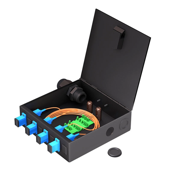
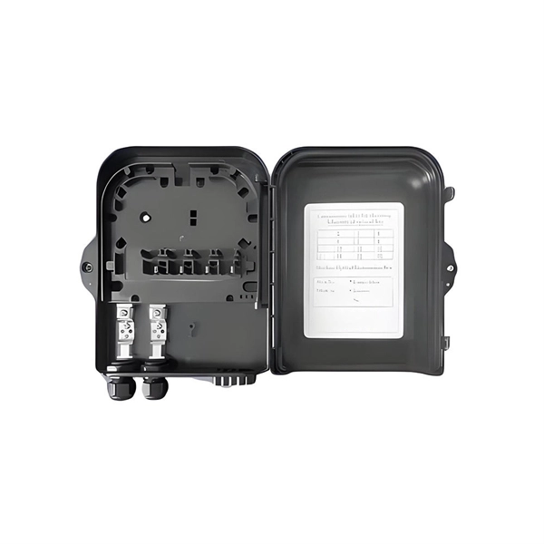
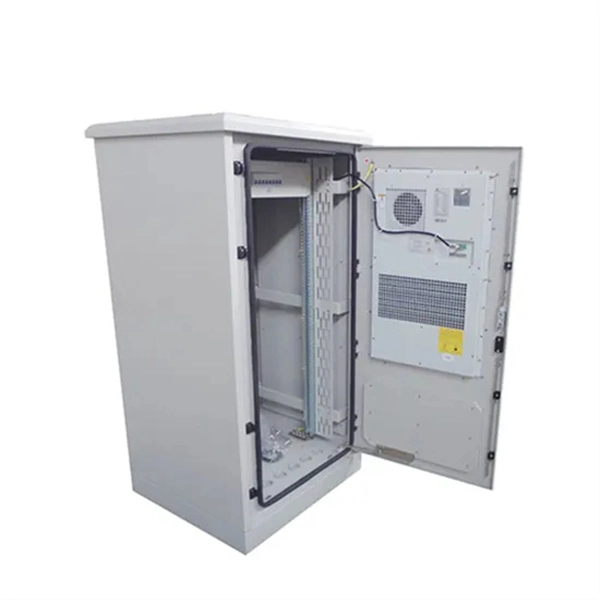
The function of a 10 Gigabit optical splitter
By dividing a single optical signal from a central Optical Line Terminal (OLT) into multiple outputs for Optical Network Terminals (ONTs) at users' homes, splitters eliminate the need for dedicated fibers to each residence—slashing infrastructure costs while scaling network reach. An Optical Splitter, also known as a beam splitter, is a passive optical device that divides a single input optical signal into two or more output signals. Conversely, it can also combine multiple signals into one. Optical splitter. Where splitters are placed in the network can make significant impacts on fiber counts, network cost and deployment time and operational steps, such as customer onboarding and maintenance. One important note is that splitting architectures should be seen as tools that can be mixed and matched to. The trick is how that single signal gets divided. That's where splitters come in.
[PDF Version]
-
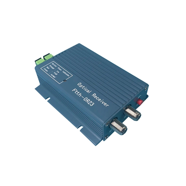
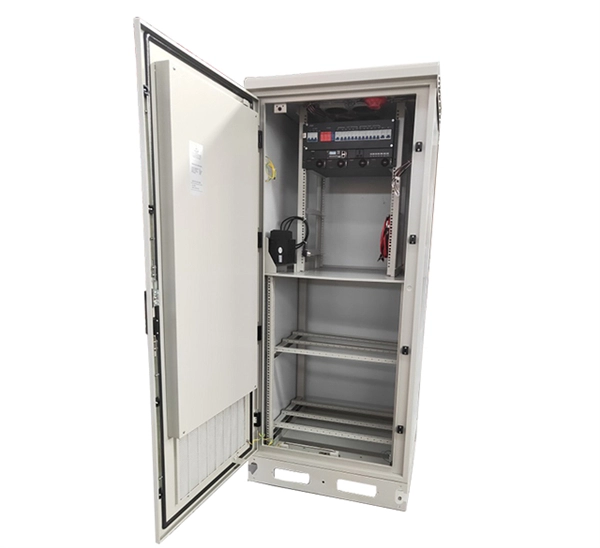
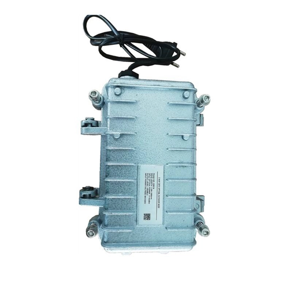
10 Gigabit Ethernet card optical module not connected to fiber optic cable
Troubleshooting SFP+ link issues in 10 GbE networks requires attention to module type, match of speed and wavelength, clean fiber connections, correct configuration, thermal management, and equipment compatibility. You can quickly resolve SFP+ Module connectivity issues by following a systematic optical transceivers troubleshooting process. Check for common connection problems, such as link failures or modules not recognized. Check compatibility between the optical module and switch Most switch brands have specific compatibility requirements. During network upgrades, many enterprise users encounter a common issue: after replacing 10G broadband lines or inserting 10G SFP+ optical modules, the switch still fails to operate at full 10G bandwidth or even fails to recognize the modules. We've listed the five most common ones. First of all, let's briefly recap what SFP and SFP+ stand for. SFPs – short for 'small form-factor pluggable' – are compact, hot-pluggable devices.
[PDF Version]
-

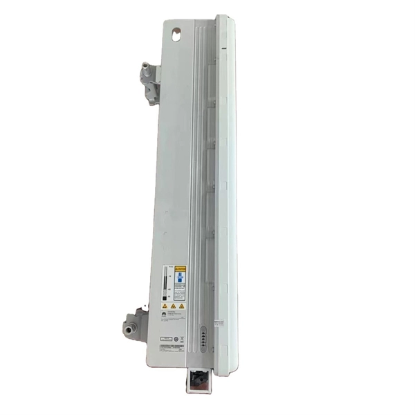
Switches are all 10 Gigabit optical
To implement different 10GbE physical layer standards, many interfaces consist of a standard socket into which different physical (PHY) layer modules may be plugged. PHY modules are not specified in an official standards body but by (MSAs) that can be negotiated more quickly. Relevant MSAs for 10GbE include (and related X2 and XPAK), and. When choosing a PHY.
-
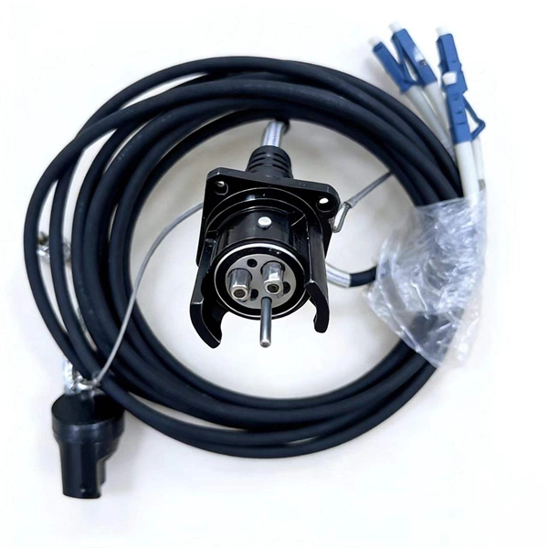
The best way to touch optical cables
Connecting an optical cable, also known as a TOSLINK cable, is straightforward: Carefully align the connector with the port, ensuring the shape matches, and gently push it in until you feel a click. This transmits audio data digitally for pristine sound quality. They consist of a fiber optic core surrounded by layers of protective material and are terminated with TOSLINK connectors. These cables are widely used due to their. Optical cables are designed to carry data in the form of light through fiber optic technology. So, it isn't supposed to be loose. Secure the cable along walls or furniture using clips, avoiding sharp bends.
-
Impact force of optical cables
This procedure provides a method to determine the ability of optical fiber cables to withstand impact loads. (b) Damage to the outer sheath. Laboratory accelerated aging environments have long been used as a measure to predict field performance of optical fiber and cables'. Fiber optic impact testing is a used to assess the resilience and durability of fiber optic cables when subjected to impact or mechanical stress. It involves subjecting the cable to various impacts or mechanical forces to evaluate its ability to withstand such events without experiencing. Fiber design and transmission technology have collaboratively evolved to increase bandwidth. Although there is an. For fiber optic cable, the tensile strength of a cable represents the highest load or pulling force that can be placed upon any cable before any damage occurs to the fibers or their optical properties and characteristics. This is not the cable breaking strength, but a realistic allowable limit. We describe how this reliability relates with the various processing steps before the cable is eventually put into service - e.
[PDF Version]
-
Spacing between communication optical cables and power cables
The National Electrical Code establishes specific minimum distances when communications cables must run near power and light circuits. This practice is mandatory for two distinct reasons: ensuring the safety of the structure and its occupants, and preserving the integrity of sensitive data. Maintaining proper separation between power, data, and limited energy cabling is foundational to system performance, safety, and code compliance. Cable design and placement are very important to ensure that electromagnetic interference (EMI), or dangerous levels of electrical energy are not induced into. (12 in) between fiber optic communications cables lashed to a steel messenger located in the communication space and power company neutral conductors located in the supply space? A third party attacher has placed new, 1⁄4 in, galvanized steel strand and lashed dielectric fiber optic communications. FIGURES.
[PDF Version]
-
How to quickly string optical cables in a cable tray
Install a simple pulley system above the cable tray. Tie the new cable to the string and pull (or push) the string through the pulleys. This document describes the specifications for preparing, routing, and bundling cables and attaching labels to these cables. cables must lay side by side with a little bit space between (as discripted on your electricity l. more In this video i am going to show you how to install cables on a. Fiber optic cable may be installed indoors or outdoors using several different installation processes. Whether you're building a commercial setup or upgrading an industrial plant, proper cable tray installation ensures neat wiring, safe access, and easy maintenance.
-
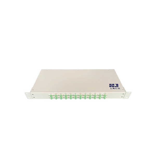
What are the uses of special optical cables in the field
While standard fiber optic cables serve well in general communication networks, specialty cables offer unique features, such as enhanced performance in extreme environments, increased data capacity, or compatibility with specific wavelengths of light. At its most basic, a fiber optic cable is composed of glass threads (optic fibers), each of which can transmit messages. Optical fibers have transformed how we communicate, connect, and transmit data. Among these, special optical fibers stand out for their tailored properties, enabling applications beyond traditional telecommunications. As technology advances, the demand for specialized optical cables has grown, leading to the development of various specialty fiber cables. HOC (Hone Optical Communications) special fiber optic cable means the optical cables used in special areas or need special structure and materials to meet the application environment. It is designed to transmit data in the form of light signals over long distances with minimal signal loss.
[PDF Version]
-
Optical fiber cables have high return loss
An fiber can have some finite return loss due to Rayleigh backscattering. This is exploited in the context of optical time-domain reflectometry, which is widely used for monitoring the status of fiber-optic links. Reflectance (which has also been called "back reflection" or optical return loss) of a connection is the amount of light that is reflected back up the fiber toward the source by light reflections off the interface of the polished end surface of the mated connectors and air. This is always measured in dB (decibels) and will be displayed as a negative number. the reflection above the fiber backscatter level, relative to the source pulse, is called reflectance. Optical return loss is given in units of dB and always a.
-
Performance of Vietnam s Conduit-Packed Optical Cables
The Vietnamese optical fiber cables market was estimated at $X in 2024, with an increase of X% against the previous year. In general, the total consumption indicated pronounced growth from 2012 to 2024:.