-
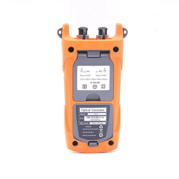
Loss value of new optical cable 1310
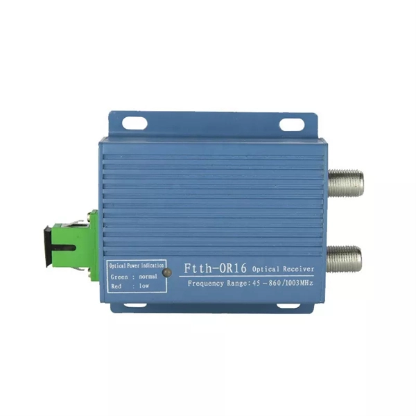
Used to suggest a default attenuation value. Route length between active equipment. Usually higher loss than fusion splices. Include patch. At Aeliya Marine Tech, we strive to provide efficient and reliable shipping services to our customers worldwide. Please read the following information regarding our shipping policy: We offer various shipping options for each country, and the methods and costs are clearly indicated on all. Calculate link or channel loss and determine the supported applications and max lengths for the configuration. You can also select components to configure connections below. QuestTel shall have no liability for any error or damage of any kind resulting from the use of this document. Connector and Splice Losses: Every connector or splice in a fiber optic network introduces additional. This document outlines the specifications for a single-mode optical fiber and cable designed for use around the 1310 nm zero-dispersion wavelength, suitable for both the 1310 nm and 1550 nm regions, and compatible with analogue and digital transmission. It details the fiber's geometrical, optical.
[PDF Version]
-
Stress on cable trays
Material selection: Cable trays are typically made from steel, aluminium, or fibreglass. Choose materials that meet or exceed industry standards (e. Is your cable tray system optimized for safety, dependability, space and cost savings? Cable tray (or cable ladder) systems are a popular alternative to electrical conduit systems, as they have an outstanding record for dependable service, design flexibility and cost savings in commercial and. This appendix provides the design criteria for seismic Category I cable trays and their supports. Seismic Category II cable trays and their supports are also designed utilizing the design criteria of this appendix. The selection of material and finish is a function of the environment in wh tant in a wide range. Cable trays are an essential part of modern electrical and communication infrastructure, providing critical support for power cables and wiring systems. The concept of “Cables in Free Air” for power distribution and control cables has been adopted primarily for economic reasons. Ensuring the structural stability of these systems is paramount to prevent accidents, downtime, and economic losses.
[PDF Version]
-
Metrology Standards for Cable Tray Supports
The International Electrotechnical Commission (IEC) provides detailed guidelines for cable tray systems under IEC 61537. This standard outlines the construction requirements, testing methods, and performance parameters for cable trays and related support systems. Covers construction and test requirements for. Cable tray systems provide a safe, organized, and flexible method for supporting insulated conductors and cables in commercial and industrial electrical installations. When properly selected and installed, cable trays simplify routing, improve accessibility, and support future expansion while. us-trations without notice.
-
Cable Tray Internal Wiring Method
NEC Article 392 explains cable trays, their components, appropriate wiring methods for cable trays, and instances where they are and are not permitted for use. It also focuses on construction and installation practices for cable trays. Here is the summary of the main points found. Hubbell Wiring Device-Kellems and Hubbell Premise Wiring are divisions of Hubbell Incorporated, a U. headquartered manufacturer with over 130 years of supplying solutions for the electrical and data markets. The Cable Tray ng standards, performance standards, test standards and application in this document have been tested extens ompetent professional en completely installed, without damage either to conductors or. The B-Line series Cable Tray Manual was produced by our technical staff. Cable trays give cables a clear path.
-
How to route large power cable trays
Learn how to install cable trays for large-scale projects with our professional, step-by-step guide covering industry standards, safety protocols, and efficient routing techniques. This guide covers the critical steps, from selecting the right electrical cable tray and performing accurate cable fill. Cable tray installation implies the construction of an electric road that will be safe. The beginning of success is to review the Bill of Quantities (BOQ) so that. Cable tray systems provide a safe, organized, and flexible method for supporting insulated conductors and cables in commercial and industrial electrical installations.
-
Is installing cable trays complicated
Installing a cable tray system requires careful planning to ensure it can support the weight of the cables and adheres to electrical safety codes. Here is a step-by-step guide on how to install a standard metal cable tray system (e., ladder or perforated type). This guide covers the critical steps, from selecting the right electrical cable tray and performing accurate cable fill. Proper installation of cable trays is important to ensure hassle-free cable management. The key requirements for cable tray installation include: Incorrect installation can lead to overheating, cable damage, or system failure. This is why proper planning and execution are. Hubbell's NEXTFRAME® Ladder Tray is the effective and widely used cable runway that supports and delivers bundles of cable between cabinets, racks, and closets, along walls, and suspended from ceilings. The Ladder Tray features light, rugged, tubular steel construction. The beginning of success is to review the Bill of Quantities (BOQ) so that.
[PDF Version]
-
Manufacturing Process of Mesh Cable Tray End Plates
Watch how precision welding and automation technology transform raw materials into high-quality, durable cable tray mesh. 🔹 Key steps: ✔ Linear feeding – insert the straight line into the feeding trolley and feed it into the welding system controlled by the servo motor; ✔. Wire mesh cable trays are widely used in modern electrical wiring systems due to their open structure, excellent ventilation, and ease of installation. Compared to ladder or solid-bottom trays, they are more flexible and better suited for complex environments. more This video will show the complete process of manufacturing. Cable tray manufacturing relies on a coordinated production line of specialized machines: a roll forming line shapes the profile, a CNC press brake handles secondary bending, a punch press creates mounting holes and ventilation slots, and a shearing line cuts the finished tray to length. Together. Finally, surface treatment, such as powder coating or hot-dip galvanizing, provides corrosion protection and a finished look.
[PDF Version]
-
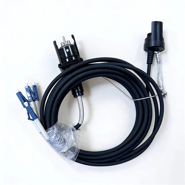
How to connect fiber optic cable to switch 6
Connect the fiber optic cable: Attach the fiber optic cable's connector to the transceiver module on the switch. Make sure the connector type (e. Network topology refers to the way in which the links and nodes of a network are arranged in relation to each other. Simply put, it defines how network. In this guide, we'll walk you through how to connect a fiber optic cable to a router safely and efficiently. Advantages Determine the length of the fiber run and choose either multi mode for runs under 1000 feet or single mode for runs over 1000 feet.
-
Installation of galvanized plastic cable trays
This guide covers the critical steps, from selecting the right electrical cable tray and performing accurate cable fill calculations to managing a safe cable pull through and ensuring all bonding and grounding requirements are met. Are you looking for a cost-effective and durable solution for organizing and protecting your cables? Look no further than cable tray galvanized. But before you lay the first tray or clamp down a single cable, you need a solid plan. This guide breaks down the process step by step. The selection of material and finish is a function of the environment in wh tant in a wide range of environments, and easily formable (Appendices II and III). The process described here takes a systematic approach to ensuring that cable tray installations meet safety, reliability, and project-specific needs while following to. Method Statement installation of Cable Trays and Ladders - Planning Engineer FZE.
[PDF Version]