-
Optical modules are used in switches
Switch optical modules, which convert electrical signals to optical signals and vice – versa, and optical interfaces, which serve as the physical connection points, play a pivotal role in determining the speed, distance, and reliability of data transmission. Everything you need to build an optical network from end-to-end. Common optical module types such as SFP. SFP (Small Form-factor Pluggable) is a compact, hot-pluggable network interface module used to connect network devices (switches, routers, firewalls) to fiber optic or copper cables. Think of it as the “translator” for your network equipment, converting electrical signals into optical signals. Describes what an optical module is and FAQs, including the fundamentals, appearance and structure, key performance counters, common types, and naming conventions of optical modules, causes of optical module failures and corresponding protection measures, types of optical modules supported by. An optical transceiver module, often simply called an optical module, acts as a signal conversion interface in fiber optic networks.
[PDF Version]
-

Switches are all 10 Gigabit optical
To implement different 10GbE physical layer standards, many interfaces consist of a standard socket into which different physical (PHY) layer modules may be plugged. PHY modules are not specified in an official standards body but by (MSAs) that can be negotiated more quickly. Relevant MSAs for 10GbE include (and related X2 and XPAK), and. When choosing a PHY.
-
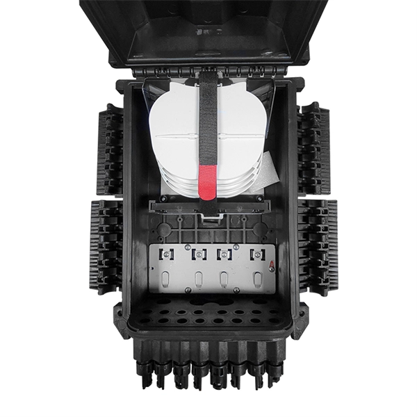
What is the fiber optic splice tray in the optical distribution box
• Splice Tray: This compartment is designed for fiber splicing and storage. It features slots or holders that secure spliced fibers, protecting them from bending, physical damage, or external stress. What is a Fiber Splice Tray Used for? With the increasing development of optical fiber networks, optical fiber terminals using fusion splicing or mechanical fusion have become common. Because optical fibers are sensitive to pulling, bending, and crushing forces, use fiber splice trays to provide. With the growth of FTTH, FTTx, and telecom fiber networks, the management of fiber optic splicing plays an increasingly important role in network reliability, performance, and maintainability. Inside splice closures, cabinets, and distribution frames, dozens or even hundreds of fibers need to be. Fiber Distribution Boxes (FDBs) are critical components in modern telecommunications infrastructure, particularly in fiber optic networks. Typically made from durable materials like plastic or.
[PDF Version]
-
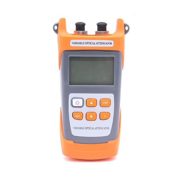
How are 36 cores of power optical fiber cable divided
Multi-core optical fiber is a breakthrough in optical networking that packs multiple cores into one fiber, enabling tremendous capacity gains via spatial division multiplexing. By carrying parallel channels in a single strand, MCF allows operators to multiply bandwidth without. These optical signals are transmitted (Tx) and received (Rx) at deliberate power levels expressed and measured in milliwatts (mW), an absolute optical power level. Absolute levels may also be represented as a relative optical power level, known decibel milliwatt or dBm. Its primary function is to split the optical signal of one input optical fiber into multiple optical signals and transmit them to. MTP/MPO cables are a class of high-density multi-core fiber optic connectivity solutions widely used in data centers and telecom networks, which are designed to achieve fast connection of multi-core fiber optics through a single interface. In contrast to conventional single-core fibers (one core on the fiber axis), MCF can have two or more.
[PDF Version]
-
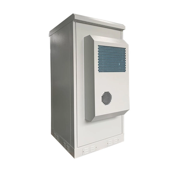
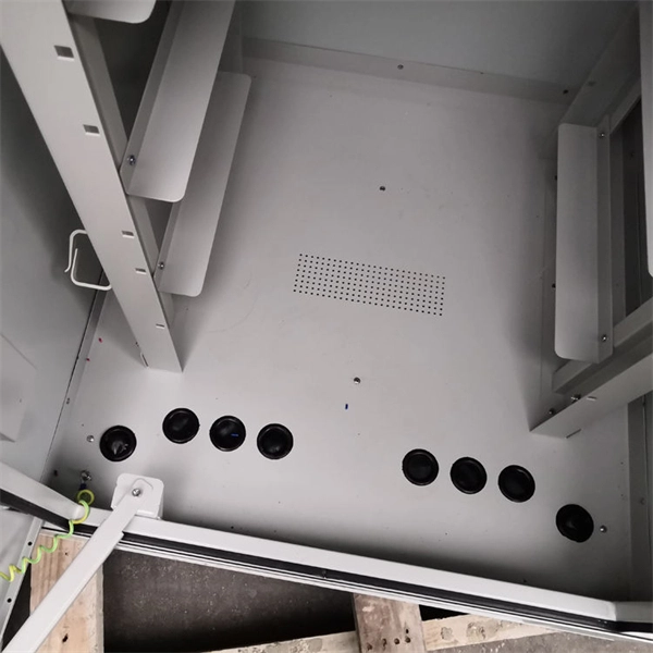
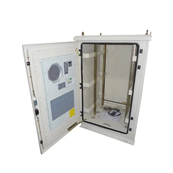
Composition of optical distribution box
It is widely adopted in FTTx cabling for both fiber cabling, provides the connection between fiber optic cables and passive optical splitters. Fiber Distribution box contains the shell, the internals (supporting frame, set fiber disc, fixing device) and optical fiber. The fiber distribution box, a crucial component in optical fiber networks, serves a dual purpose of managing and protecting optical fibers while facilitating their efficient distribution. Whether you're building a central office, data center, or FTTx distribution network, understanding the right ODF. ication and relevant standards over the range of optical wavelengths from 1260nm to 1625nm. However, component desi n should also take account of future requirements to extend operating wavelength to 1675nm. Cross-con-nections and direct connection can be two ways to.
[PDF Version]
-
How is the serial interface of the XFP optical module
The XFP 2-wire serial interface is used for serial ID, digital diagnostics, and certain control functions. It was defined by an industry group in 2002, along with its interface to other electrical components, which is called XFI. XFP modules can be installed or replaced in an Extreme Networks switch, I/O module, or router without powering off the system. All Extreme Networks XFP modules comply with. This Juniper Networks® XFP-10G-S compatible XFP transceiver provides 10GBase-SR throughput up to 300m over multi-mode fiber (MMF) using a wavelength of 850nm via an LC connector. It can operate at temperatures between 0 and 70C. The transceiver is compliant with CPRI, eCPRI. With these features, this 10G SFP+. ID systems defined for the GBIC and SFP transceivers. 12 document apply to Beta-and Production-level units only. Physical Medium Dependent (PMD) sublayer and baseband medium, type 10GBASE-S (short wavelength serial), 10GBASE-L (long wavelength serial), and.
[PDF Version]
-
How to locate the fault point in a communication optical cable
Struggling to identify faults, validate polarity or ensure quality mechanical connector terminations in your fiber optic cables? Visual Fault Locators (VFLs) are a valuable tool that make troubleshooting fast and efficient. Let's dive into everything you need to know about mastering VFLs. Common Indicators of a Cable Break Signal Loss or Interruption: If data transmission is interrupted, it could indicate a break or severe bend. Physical. Finding a fiber fault typically involves the following steps: 1. However, physical damage can disrupt this infrastructure and cause significant network issues. When fiber cables sustain damage, specialized repair techniques help. To ensure the quality and continuity of fiber optic services, it is essential to identify and locate fiber optic cable faults as quickly and accurately as possible.