-
-
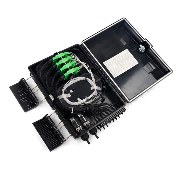
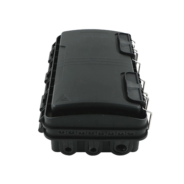
The function of the switch in the distribution box
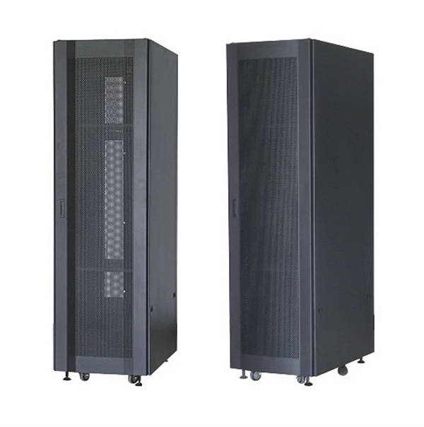
The main switch, or main breaker, controls the entire electrical supply to the distribution box. It's typically rated for the maximum current capacity of the electrical. A distribution box, also known as a distribution board, electrical panel, or breaker box, is an enclosure that houses electrical components responsible for distributing electricity throughout a building. Unlike. Isolation switches in distribution boxes ensure electrical safety by disconnecting circuits for maintenance, preventing shocks, aiding compliance, and improving system reliability. This switch allows for the isolation of power during maintenance or emergencies. Understanding its significance. -
-

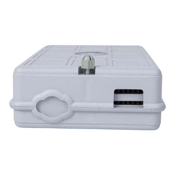
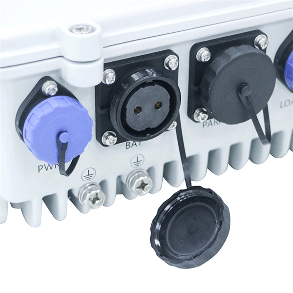
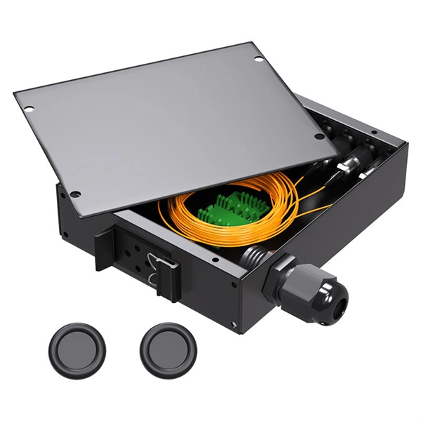
How to calculate the capacity of a construction site electrical distribution box
The calculator employs NEC Article 314. 16 formulas to determine required box volume. The basic formula is: Required Volume = (Number of Conductors × Volume per Conductor) + (Number of Devices × 2 × Volume per Conductor) + (Number of Fittings × Volume per Conductor). Calculate electrical box fill capacity and ensure NEC compliance for proper wire management and electrical safety. (Exact counting rules and allowed fill depend on your electrical code and installation details. -
-
-
-
-
-
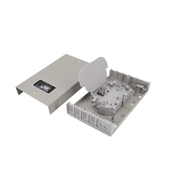
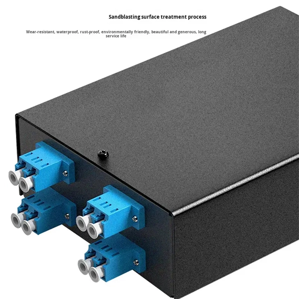
No network connection when the switch is plugged into the optical port
The first thing you should do is re-plug the optical module into the switch slot and make sure it is firmly inserted. Tip #3: Why is there no link after connecting two. This document describes how to troubleshoot fiber optic interfaces by addressing some of the fiber optic module and cabling specifications. There are no specific requirements for this document. When the connection does not work as expected after we set it up according to the Installation Guide, we need to do some troubleshooting. When a switch refuses to detect a module, a link light won't illuminate, or performance degrades without warning, you need more than guesswork. You need a clear, step-by-step SFP troubleshooting guide that helps you restore connectivity quickly and confidently. This guide addresses real-world. Usually, the port status failures are manifested as four types: the port is down (link failure), no packets received or sent when the port is up, unstable link, and CRC errors. You can troubleshoot those issues from the following four perspectives: Take the 10G SFP+ optical modules as an example. modern networking, SFP ports (Small Form-factor Pluggable ports) play a critical role by enabling flexible connectivity using either fiber optic or copper connections. -

-