-
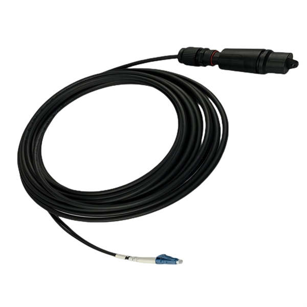
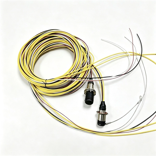
Fiber optic cable outer sheath representation
1 The outer cable jacket shall be marked with the manufacturer's name, date of manufacture, fiber count, fiber type, flame rating, listing symbol, and sequential length markings every two feet (e., “CORNING OPTICAL COMMUNICATIONS OPTICAL CABLE - MM/YY. XXXXX (feet. One important consideration when selecting indoor fiber optic cables is the outer sheath material and its fire prevention level. Each cable is single packed in a polybag with a test report that guarantees best performance in typical application scenarios like telecommunication, rack cabling, sensor technologies or indust Choosing the appropriate outer sheath material for fiber optic cables is crucial for ensuring the cable's durability, protection, and performance under specific environmental conditions. At the same time, it must have. 1. 1 The cable shall meet all requirements stated in this specification. Glass fiber and plastic fiber is fragile.
[PDF Version]
-
AI-powered Fiber Optic Cable Maintenance
By integrating Fiber Optic Internet with AI-powered predictive maintenance tools, organizations can monitor their equipment in real-time and anticipate potential failures before they occur. To keep up with this rapid growth, the integration of cutting-edge technologies like Artificial Intelligence (AI) and Machine Learning (ML) is essential for optimizing. This article explores how AI's exponential growth is creating transformative demands on fiber optic cables, connectivity solutions, and the broader communications industry, and what innovative approaches manufacturers must adopt to meet these challenges. Machine learning models can adapt their behavior to changing network conditions, traffic patterns.
-
Metrology Standards for Cable Tray Supports
The International Electrotechnical Commission (IEC) provides detailed guidelines for cable tray systems under IEC 61537. This standard outlines the construction requirements, testing methods, and performance parameters for cable trays and related support systems. Covers construction and test requirements for. Cable tray systems provide a safe, organized, and flexible method for supporting insulated conductors and cables in commercial and industrial electrical installations. When properly selected and installed, cable trays simplify routing, improve accessibility, and support future expansion while. us-trations without notice.
-

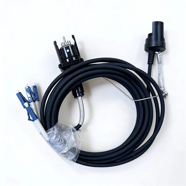
What does a 72-core optical cable look like
GYTA53 fiber cable consists of 250um fibers held in gel-filled PBT loose tubes, and wrapped around a phosphatized steel wire central strength member. A waterproof compound fills the loose tube, and the center of the cable core is a metal reinforced core. 72 core fiber optic cable should be selected by fiber standard, cable structure, jacket, tensile strength, installation route, drum length, testing, and quantity. single mode GYTA53 fiber optic cable and multimode. Fibertronics' Fiber Optic Distribution Cable is composed of high quality colored tight buffers, aramid yarn and a PVC outer jacket. Their small bend radius allows for fast installations and easy terminations within confined. Corning ribbon plenum cables are designed for use in plenum, riser and general purpose environments for intrabuilding backbone installations and for high-fiber-count data centers.
[PDF Version]
-
Do cables have to be run in cable trays
Answer: Yes; cables are tied down in cable trays to keep the cables in the cable tray, to maintain spacing between cables, or to segregate or confine certain types of cables to specific locations. The last two items can also be accomplished with a solid fixed barrier. Cable tray types, fill rules for single-conductor and multiconductor cables, ampacity derating, separation requirements, and when to use tray vs conduit. Cable tray is the preferred wiring method for industrial facilities, data centers, and large commercial buildings where routing dozens or. Cable tray barriers can be used to separate conductors operating over 600 volts from other conductors in the same tray operating at 600 volts or less. Code Change Summary: A clarification was made regarding separation of conductors in cable trays when conductors operate at different voltage levels. This is a description of how to select, install, and support these metal or plastic frames, on which electrical wires are installed. You should consider it as a series of instructions that make the buildings resistant to. Article 392 of the NEC provides the basic requirements for installations using cable tray.
[PDF Version]
-
Translate the cable tray by 45 degrees
To create a 45-degree bend, cut the side rails to remove a segment calculated by the formula (Tan (22. Google's service, offered free of charge, instantly translates words, phrases, and web pages between English and over 100 other languages. So basically from my middle line what size to mark either side to cut my lip away to create different angles. Calculate horizontal, vertical, or compound cable tray offsets based on bend angle, offset distance, and available installation space. Measure this distance along the straight tray. ADVANCED S PRODUCTS I ASP 45° inuous system as well as stand-alone elements. 5∘ cuts on two separate pieces of cable tray. The second piece's cut must be in the opposite direction. Easy step to make 45 degree offset cable tray/Pipe and Air duct Cable tray 90 Degree Bend ! Cable tray ( Hindi) Cable tray 22. Distance of 145 mm ×.
[PDF Version]
-
Manufacturing Process of Mesh Cable Tray End Plates
Watch how precision welding and automation technology transform raw materials into high-quality, durable cable tray mesh. 🔹 Key steps: ✔ Linear feeding – insert the straight line into the feeding trolley and feed it into the welding system controlled by the servo motor; ✔. Wire mesh cable trays are widely used in modern electrical wiring systems due to their open structure, excellent ventilation, and ease of installation. Compared to ladder or solid-bottom trays, they are more flexible and better suited for complex environments. more This video will show the complete process of manufacturing. Cable tray manufacturing relies on a coordinated production line of specialized machines: a roll forming line shapes the profile, a CNC press brake handles secondary bending, a punch press creates mounting holes and ventilation slots, and a shearing line cuts the finished tray to length. Together. Finally, surface treatment, such as powder coating or hot-dip galvanizing, provides corrosion protection and a finished look.
[PDF Version]
-
Stress on cable trays
Material selection: Cable trays are typically made from steel, aluminium, or fibreglass. Choose materials that meet or exceed industry standards (e. Is your cable tray system optimized for safety, dependability, space and cost savings? Cable tray (or cable ladder) systems are a popular alternative to electrical conduit systems, as they have an outstanding record for dependable service, design flexibility and cost savings in commercial and. This appendix provides the design criteria for seismic Category I cable trays and their supports. Seismic Category II cable trays and their supports are also designed utilizing the design criteria of this appendix. The selection of material and finish is a function of the environment in wh tant in a wide range. Cable trays are an essential part of modern electrical and communication infrastructure, providing critical support for power cables and wiring systems. The concept of “Cables in Free Air” for power distribution and control cables has been adopted primarily for economic reasons. Ensuring the structural stability of these systems is paramount to prevent accidents, downtime, and economic losses.
[PDF Version]