-
Increase the light output power of the optical module
An optical amplifier is a device which receives some input signal light and generates an output signal with higher optical power. Typically, inputs and outputs are laser beams (very rarely other types of light beams), either propagating as Gaussian beams in free space or in a fiber. At the receiver end, the optical signals are reconverted into electrical. In this guide, we will explain what optical signal strength is, how to check it on Cisco IOS using the command line, and how to troubleshoot common light level issues. Assume the. This application note gives a short introduction to optical modules and the need of an optimized power tree in them and then concentrates on the use cases and benefits of four-switch and inverting buck-boost converters inside optical modules.
-
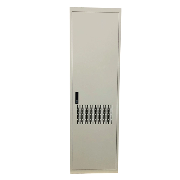
Function of the small busbar in the central power switch
The bus bar is a metal strip that distributes electrical current to the individual circuit breakers. In most assemblies you will find horizontal main bars, vertical risers, neutral and equipment-ground buses, and purpose-designed. What are Busbars, Bus Stabs, Circuit Spaces, Breaker Slots, Neutral Terminals, and Ground Terminals in an Electrical Panel or Load Center? Electric panels and load centers in residential and commercial applications have some different setting for breaker installation ad load circuit distribution. They connect directly to the main power source and are designed to handle high current loads safely. Circuit Breakers act as protective devices within the panel.
-
Incident Power in Fiber Optic Communication
The incident optical power is used to suppress nonlinear effects and ensure transmission quality. In the following figure, optical power at point C is the incident optical power. Why Do We Need Incident Optical Power? The transmission performance of a WDM system is affected by the. This AE Note explains the differences between Optical Return Loss (ORL) and Back Reflectance in fiber optic systems. Even minor deviations—whether too high, too low, or unstable—can impact signal integrity, trigger service alarms, or interrupt traffic on DWDM, OTN, or long-haul optical line systems.
-
How to determine light attenuation of red light using an optical power meter
Optical attenuation compares input and output power on a logarithmic scale. When powers are in linear units, the loss in decibels is: Attenuation (dB) = 10 × log10 (Pin / Pout) If the link length L is provided, the attenuation coefficient is: Coefficient (dB/km) =. Analyze optical power drop across fibers and links. Switch units, lengths, and calculation modes easily. Needed when attenuation is an. Optical power, required for measuring source power, receiver power and, when used with a test source, loss or attenuation, is the most important parameter and is required for almost every fiber optic test. Backscatter and wavelength measurements are the next most important and bandwidth or. Optical power meters are a key element in the optimization and maintenance of such optical networks and of their components. But, for designers, just starting to work in the fiber-optic design space, measuring attenuation can seem like a monumental task.
[PDF Version]
-
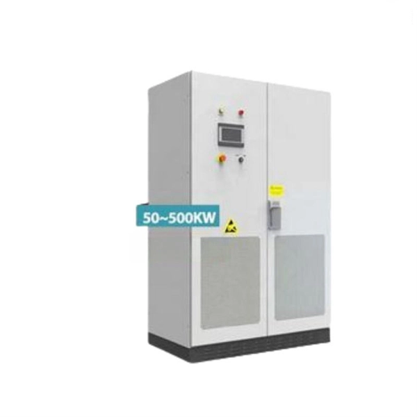
Integrated AC Power Supply System
The images below show a design example involving an isolated power supply. In this supply, we actually have two levels of isolation applied between the input and output: 1. Initially at the AC input 2. Betwee.
-
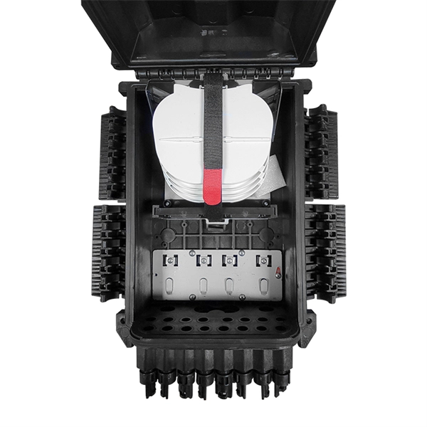
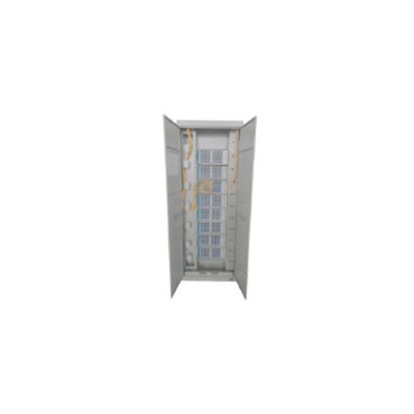
How are 36 cores of power optical fiber cable divided
Multi-core optical fiber is a breakthrough in optical networking that packs multiple cores into one fiber, enabling tremendous capacity gains via spatial division multiplexing. By carrying parallel channels in a single strand, MCF allows operators to multiply bandwidth without. These optical signals are transmitted (Tx) and received (Rx) at deliberate power levels expressed and measured in milliwatts (mW), an absolute optical power level. Absolute levels may also be represented as a relative optical power level, known decibel milliwatt or dBm. Its primary function is to split the optical signal of one input optical fiber into multiple optical signals and transmit them to. MTP/MPO cables are a class of high-density multi-core fiber optic connectivity solutions widely used in data centers and telecom networks, which are designed to achieve fast connection of multi-core fiber optics through a single interface. In contrast to conventional single-core fibers (one core on the fiber axis), MCF can have two or more.
[PDF Version]
-
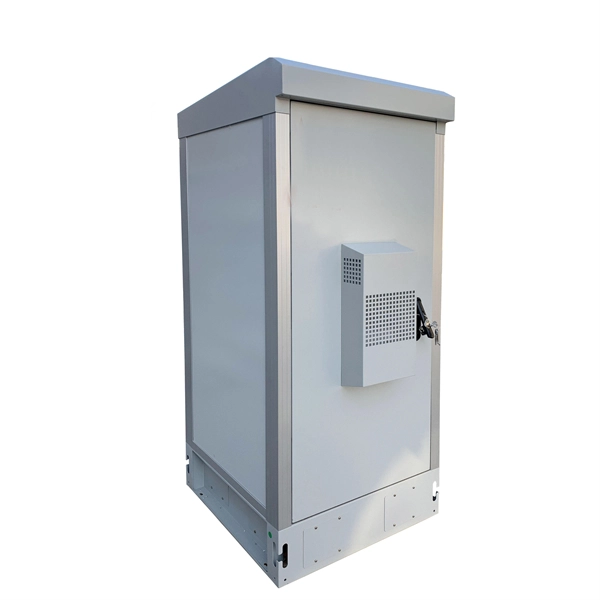
48V power supply for communication sites used in subways
This article presents a scalable and stackable –48 V DC PoL solution that will address the high density power usage situations created by these high density networks from the tremendous growth in network traffic. converting unstable AC input into stable, regulated 48V DC power for telecom equipment. Integrated DC system capability with controller and distribution module options, allow customers to have a complete DC Power System in 1U height. As DC power. The LXPower48200S is specially designed to meet the demand for compact, flexible, high performance, high reliability power supply. The system consists of 1-4 units LXPower3000 high/standard efficiency rectifier modules of their mixture, a LX2000 monitor module, AC/DC distributors. Because DC. The choice of -48V DC for powering telecommunications equipment is a standard practice rooted in a blend of historical precedent and a suite of technical benefits that ensure the robust, efficient, and safe operation of telecommunications networks. This standard is not arbitrary but is the result.
[PDF Version]
-
What type of fiber optic cable is used for power transmission towers
Optical Ground Wire (OPGW) cable is a type of fiber optic cable that is specifically designed for use in overhead power transmission lines. These cables are made up of extremely thin strands of glass or plastic, known as optical fibers, which are encased in protective sheathing. The fibers are arranged in. Besides the use of special cables on transmission and distribution towers or poles, the installation of fiber optic cables for utilities may require the shutdown of electrical distribution for installation, although some installations are possible without shutdown. Such cable combines the functions of grounding and telecommunications. The all-dielectric design eliminates.
-
Outdoor power distribution box missing zeros
Check the electrical load and ensure that the sensors do not exceed the 10 Amp maximum. Whether you're managing industrial sites, renewable energy projects, or commercial facilities, this guide explains practical solutions to diagnose and fix missing phase issues efficiently. A. To quickly rule out potential culprits, check these things in this order: GFCI reset at an outlet inside the house. Get free shipping on qualified Outdoor Breaker Boxes products or Buy Online Pick Up in Store today in the Electrical Department. This value kit includes six 20 Amp Single-Pole, one 30 Amp Double-Pole, one 50 Amp Double-Pole THQL 1 in. The load center includes a sturdy tin-plated copper buss bar and a galvanized box for increased durability and reliability. The one-piece interior removes and re-installs. INDU-ELECTRIC proudly presents the Cube® Series—our most compact line of non-conductive power distribution boxes, engineered for professional use in demanding environments like construction sites, stages, film sets, and live events.
[PDF Version]
-
Power Grid Optical Cable Operation Level
Key OPGW testing methods include visual inspection, OTDR testing, optical power meter testing, continuity tests, and various mechanical and environmental tests. Each method targets a specific aspect of cable performance and safety. OPGW stands for Optical Ground Wire. These cables are used on high voltage power lines. I have managed many projects where I personally oversaw the testing process. I know that if testing. This specification defines the design, material, performance and test requirements for fibre optic cable to support the fibre optic telecommunication needs. How to calculate the required fault. ion infrastructure. Optical Ground Wire (OPGW)/Underground Fiber Optic Cable (UGFO) plays a crucial role in ensuring seamless data exchange, real-time monitoring, and reliable operati n of power systems. However, with increasing demands and multiple stakeholders involved in fiber usage, it became.
[PDF Version]
-
Does an optical power meter need to be calibrated after purchase
All test equipment must be calibrated on an annual basis. Calibration ensures that the test results you are measuring are indeed accurate. EXFO can help save both time and costs with an automated calibration test system that is designed for the verification of power meters, attenuators, sources and optical time-domain reflectometers (OTDRs). This application note demystifies how EXFO's IQS-12002 Optical Calibration System can guide. Below are general answers on how to operate, maintain, and calibrate an optical fiber ranger from the list of GAO Tek's optical power meters. Power On: Ensure the device is charged or properly connected to a power source. Select. n light source as shown below. Next press and hold the Mode Button until you hear a short. A send"'optical power meter is correctly calibrated when using a equivalent testing practices. For RF sensors, address mismatch uncertainty; for optical.
[PDF Version]