-
How to view the IP address of a specific port on an access switch
Go to the Core and run show arp vlan and from the output identify and note the MAC address of the IP you are looking for. Maybe you have to reboot the WIFI device and then run a SHOW ARP *Issue is something has to PING it or communicate with it via IP for it to be in the ARP table. (That's why I say reboot it) The Access Point doesn't have a CONSOLE port? Unless the switch is in. What is the method at the command line on a 3750x switch to find out what the IP address of the connected device (Server, PC etc) which is connected to a certain port on the switch? For example. The procedure involves two key steps: First, use the mac address-table to map the. If I know the port and MAC, how do I look up it's IP from inside the extreme switch? 08-29-2018 01:26 PM let me see if we can get a couple of things defined. We'll assume a basic understanding of networking concepts, including IP addressing, subnetting, and VLANs. Show IP address for ports HP2920 switch I am trying to get which IP is connected to which port.
[PDF Version]
-
Connecting the switch s gigabit optical port to the router
The SFP port is a built-in optical port of a Gigabit Ethernet switch, so it cannot be directly connected with a twisted pair or a jumper. It needs to be connected to an optical module first, and then it can be transmitted with an optical fiber patch cord. Cisco introduces GPON with the Catalyst GPON platform. First of all, you need to unplug all the power supplies of your cable modem, wireless router and network switch. Once this is done, take one end of an Ethernet. To connect your fiber optic cable to a router, ensure you have the following: Fiber optic modem (ONT): Most fiber connections require an Optical Network Terminal (ONT), provided by your ISP. You can use the switch to connect Ethernet devices such as computers, file servers, printers, routers, switches, or hubs. Find a flat horizontal surface or a 19-inch rack.
[PDF Version]
-

Is the H3C switch an optical port or an electrical port
H3C S1850V2-X switch series comes with standard Gigabit copper ports and Ten-Gigabit optical ports, making it a good fit for complex network environments and network expansion. H3C FS6300V2-EI series switches are a new generation of high-performance, high-port density, high-security Layer 3 Ethernet switches developed by H3C Technology Co. (hereinafter referred to as H3C) using industry-leading ASIC technology, supporting IPv4/IPV6 Dual-stack management and. A Combo port can operate as either an optical port or an electrical port. Inside the device there is only one forwarding interface. You can specify a Combo port to operate as an electrical port or an. This video provides a comprehensive guide on configuring and troubleshooting Combo ports on H3C Ethernet switches. Reasonable cable routing can improve efficiency by facilitating installation and removal of fan trays, and some other components. Interface cables are routed through the. Packaging Details:1. Rated voltage range: -48 ~ -60V DC.
[PDF Version]
-
Which port on the switch is the optical interface
The optical port of an industrial Ethernet switch refers to the optical fiber interface, which has single-mode, multi-mode, gigabit, and gigabit specifications. Port types are limited to two: optical and Ethernet. RJ45 ports serve access-layer copper connections; SFP/SFP+ ports enable flexible 1G/10G uplinks; SFP28 delivers 25G for modern data centers; QSFP+ and QSFP28 support high-density 40G/100G spine–leaf. GBIC is an interface device that converts gigabit electrical signals into optical signals. This design enables end-to-end optical signal transmission, avoiding the conversion between electrical and. The optical ports on the switch are usually paired together, with one TX sender and one RX receiver. The. Most SFP fiber optic modules use LC connectors, while SC connectors are mainly found in legacy networks and MPO/MTP connectors are used for high-density cabling rather than directly on standard SFP modules. This connector landscape reflects how modern SFP deployments prioritize port density and.
[PDF Version]
-
How to convert an electrical port to an optical port on a switch
A switch SFP port converts electrical signals into optical signals via SFP transceivers, or maintains them electrically for copper connections. By using an SFP to RJ45 adapter (e. 5G SFP), you can seamlessly connect legacy Ethernet devices to modern fiber-optic. The RJ45 port is a built-in electrical port of a Gigabit Ethernet switch, and it is mainly connected by Category 5, Category 5e, Category 6, and Category 6e twisted-pair cables. However, modern networks often combine both technologies. The good news: you can bridge them easily using the right hardware, such as media. An SFP port on a switch or router SFP port enables network engineers to connect multiple media types, from fiber optic links to copper Ethernet. An SFP transceiver acts as a compact, hot-swappable optical transceiver that.
-
The function of the optical port of the switch
This device is a small transceiver you plug into a switch, router, or server. It can also turn optical signals back into electrical signals for copper cables. This lets you. Optical switching represents a fundamental technological evolution, shifting data routing from the domain of electrons to the realm of photons, or light. They're a core component in fiber-optic networks, where data travels as pulses of light through glass fibers. This lets you send data far away. SFP modules work in many network. An SFP (Small Form-factor Pluggable) is a compact, hot-pluggable transceiver module that allows networking equipment — including switches, routers, servers, and media converters — to support different physical media, such as optical fiber or copper, without replacing the host hardware.
-
Which port on the fiber optic access switch
The SFP port is commonly found on Gigabit Ethernet switches and is primarily used for fiber optic device connections or for uplinking 1G switches to aggregation/core layer devices, providing higher-bandwidth links. Unlike fixed RJ45 copper ports, SFP ports support both fiber and copper modules, enabling far longer distances, greater flexibility, and improved scalability in enterprise. It introduces common Ethernet switch port types. We will look at data rates, functions, and network architecture. This guide is especially useful when selecting a 1G campus switch or upgrading to higher-performance Ethernet solutions. They come in various form factors such as SFP, SFP+, QSFP+, and XFP. Switches with SFP ports can. The Gigabit Interface Converter (GBIC) or Small Form-factor Pluggable (SFP) port is a modular interface that offers flexibility to network administrators in terms of their networking hardware. These ports use twisted-pair copper cables (Cat5e, Cat6, Cat6a, etc.
[PDF Version]
-
Change the core switch port to trunk
How to Enable Trunking on Cisco Switch A trunk port carries many VLANs over one link between switches using 802. You turn it on with "switchport mode trunk" on the connecting interfaces at both ends. 1Q trunks, the switches maintain one spanning-tree instance for each VLAN allowed on the trunks. Then you. Master 802. Trunk links form the backbone of multi-VLAN networks on Cisco Catalyst switches. The configuration guide states “The interface becomes a trunk interface if the neighboring interface is.
-
Switch optical port indicator light status
Port Status LED - Indicates that the port status mode is selected when the LED is green. When selected, the port LEDs will display colors with different meanings. Understanding the lights on your network or Ethernet ports is essential for maintaining a stable and reliable network. For enterprise IT teams and engineers using Router-switch devices, these LEDs are often the first indicator of network health. This guide unpacks what Ethernet port LEDs mean, how vendors map colors and blink rates, and how to. System activity and status can be determined through the activity of the LEDs on the switch.
-
The switch s optical port light is red
It flashes green during the initialization phase, remains solid green after successful initialization, and turns red when a system fault occurs. When the Status light is red, you can use a PC super terminal to confirm whether the switch's software is running normally. PoE mode is enabled and Port LEDs function as described in Port LEDs and Modes, on page 3. The S3100 series does not have a Power indicator. S3100 SERIES SWITCHES TROUBLESHOOTING GUIDE. The status LEDs can display solid amber or flash during boot, POST, or other diagnostic tests. Power: This LED will light green after poweringthe Switch on to indicate the ready state of. Ethernet ports use LEDs to communicate link and activity status: Solid Green (Link) – Connection established and stable. Blinking Green (Activity) – Data is actively being transmitted. Amber / Orange (Solid or Blinking) – Indicates slower speed, configuration mismatch, or minor network errors.
[PDF Version]
-
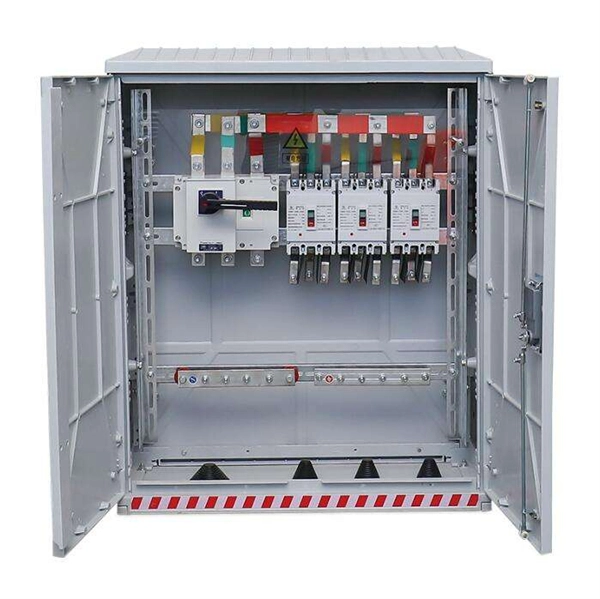
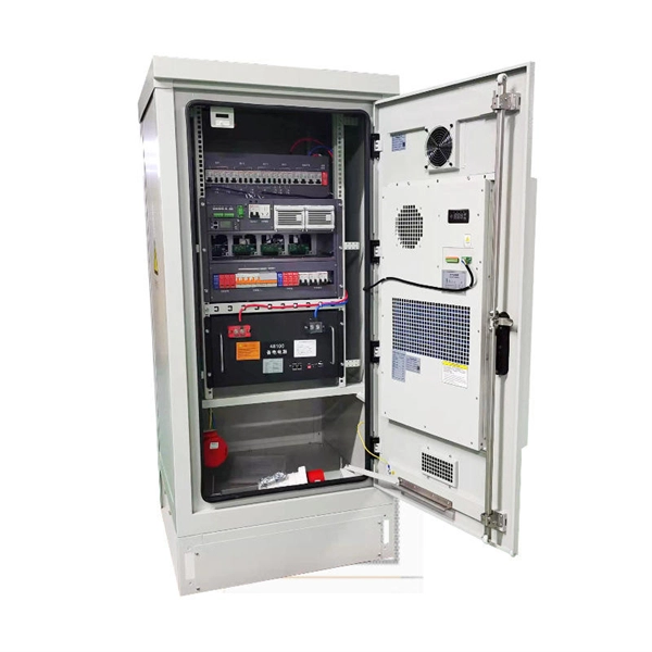
Switch cabinet busbar installation
In North America, follow UL 891 construction and NEC Article 408 installation practices: use listed/approved hardware, lugs, or tap-off provisions intended for the bus. The matrix below helps engineers finalize material, arrangement, plating/insulation, and verification. The GRL busbar system makes distribution cabinet installation fast, flexible, and neat. At this stage, the supports have been installed in accordance with the installation plan. Ever wondered how busbars, the unsung heroes of electrical distribution, are processed and installed? This article delves into the intricate steps of busbar selection, preparation, and installation, ensuring efficient and safe power distribution. The application of these rules means strict compliance, not only with applicable regulations and standards, but also with manufacturers'. Bus bars play a crucial role in electrical distribution systems by providing a reliable and efficient way to conduct electricity within electrical panels.
[PDF Version]